AgileX SCOUT 2.0 User Manual
Hide thumbs
Also See for SCOUT 2.0:
- User manual (34 pages) ,
- User manual (39 pages) ,
- User manual (48 pages)
Table of Contents
Advertisement
Quick Links
Advertisement
Table of Contents

Related Manuals for AgileX SCOUT 2.0


Summary of Contents for AgileX SCOUT 2.0
- Page 1 SCOUT 2.0 AgileX Robotics Team User Manual 2020.08 V.2.0.0...
- Page 2 If you have any questions about use, please contact us at support@agilex.ai. Please follow and implement all assembly instructions and guidelines in the chapters of this manual, which is very important. Particular...
- Page 3 Use SCOUT2.0 always under -20℃~45℃ ambient temperature. This robot does not have a complete autonomous mobile robot, If SCOUT 2.0 is not configured with separate custom IP including but not limited to automatic anti-collision, anti-falling, protection, its water and dust protection will be IP22 ONLY.
-
Page 4: Table Of Contents
CONTENTS 3.5 Firmware upgrades 1. Introduction 3.6 Use example of SCOUT 2.0 SDK 1.1 Component list 1.2 Tech specifications 3.7 Use example of SCOUT 2.0 ROS Package 2. The Basics 4. Precautions 2.1 Status indication 4.1 Battery 2.2 Instructions on electrical interfaces 4.2 Operational environment... -
Page 5: Introduction
CAN / RS232 DJI RC transmitter is provided (optional) in the factory setting of SCOUT 2.0, which allows users to control the chassis of robot to move and turn; CAN and RS232 interfaces on SCOUT 2.0 can be used for user’ s customization. -
Page 6: The Basics
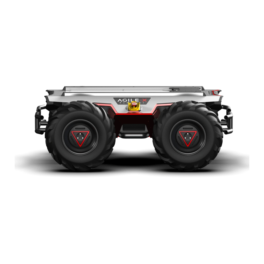
2 The Basics This section provides a brief introduction to the SCOUT 2.0 mobile robot platform, as shown in Figure 2.1 and Figure 2.2. 1.Figure 2.1 Front View 2.Stop Switch Figure 2.1 Front View 3.Standard Profile Support 4.Top Compartment 5.Top Electrical Panel 6.Retardant-collision Tube... -
Page 7: Status Indication
Figure 2.3 Schematic Diagram of SCOUT 2.0 Electrical Interface on Top SCOUT 2.0 has an aviation extension interface both on top and at rear end, each of which is configured with a set of power supply and a set of CAN communication interface. These interfaces can be used to supply power to extended devices and establish communication. -
Page 8: Rear Electrical Interface
It should be noted that, the extended power supply here is internally controlled, which means the power supply will be actively cut off once the battery voltage drops below the pre-specified threshold voltage. Therefore, users need to notice that SCOUT 2.0 platform will send a low voltage alarm before the threshold voltage is reached and also pay attention to battery recharging during use. -
Page 9: Instructions On Remote Control
2.5 Instructions on lighting control Lights are mounted in front and at back of SCOUT 2.0, and the lighting control interface of SCOUT 2.0 is open to the users for convenience. Meanwhile, another lighting control interface is reserved on the RC transmitter for energy saving. -
Page 10: Getting Started
SCOUT 2.0 vehicle body; Basic operating procedure of remote control: After the chassis of SCOUT 2.0 mobile robot is started correctly, turn on the RC transmitter and select the remote-control mode. Then, SCOUT 2.0 platform movement can be controlled by the RC transmitter. - Page 11 Table 3.1 Feedback Frame of SCOUT 2.0 Chassis System Status Command Name System Status Feedback Command Sending node Receiving node Cycle (ms) Receive-timeout (ms) Decision-making control Steer-by-wire chassis 0x151 20ms None unit 0x08 Data length Data type Function Description Position...
- Page 12 [1]: The subsequent versions of robot chassis firmware version after V1.2.8 [3]: The over-temperature protection of motor drive and the motor are supported, but previous versions need to be updated before over-current protection will be internally processed. When the supported. temperature of motor drive is higher than the protective [2] The over-temperature alarm of motor drive and the motor over-current temperature, the drive output will be limited, the vehicle will slowly...
- Page 13 Note 1 - Control mode instructions In case the RC transmitter is powered off, the control mode of SCOUT 2.0 is defaulted to command control mode, which means the chassis can be directly controlled via command. However, even though the chassis is in command control mode, the control mode in the command needs to be set to 0x01 for successfully executing the speed command.
- Page 14 Table 3.5 No.1 Motor Information Feedback Command Name No.1 Motor Drive Information Feedback Frame Sending node Receiving node Cycle (ms) Receive-timeout (ms) Steer-by-wire chassis Decision-making control unit 0x200 20ms None Data length 0x08 Position Function Data type Description byte [0] No.1 drive current higher 8 bits unsigned int16 Actual current X 10(with an accuracy of 0.1A)
- Page 15 Table 3.7 No.3 Motor Information Feedback Command Name No.2 Motor Drive Information Feedback Frame Sending node Receiving node Cycle (ms) Receive-timeout (ms) Steer-by-wire chassis Decision-making control unit 0x202 20ms None Data length 0x08 Position Function Data type Description byte [0] No.3 drive current higher 8 bits unsigned int16 Actual current X 10(with an accuracy of 0.1A)
- Page 16 Table 3.9 Lighting Control Frame Lighting Control Frame Command Name Sending node Receiving node Cycle (ms) Receive-timeout (ms) Decision-making Steer-by-wire chassis 0x140 25ms None control unit Data length 0x08 Position Function Data type Description 0x00 Control command invalid byte [0] Lighting control enable flag unsigned int8 0x01 Lighting control enable...
-
Page 17: Communication Using Can
BLACK :GND(negative pole) transmitter. Then, switch to the command control mode, i.e. toggling S1 mode of DJI RC transmitter to the top. At this point, SCOUT 2.0 chassis will BLUE :CAN_L accept the command from CAN interface, and the host can also parse the YELLOW :CAN_H current state of chassis with the real-time data fed back from CAN bus. - Page 18 Protocol specification Checksum Start bit Frame length Command type Command ID Data field Frame ID composition frame_L CMD_TYPE CMD_ID data [0] data[n] frame_id check_sum byte 1 byte 2 byte 3 byte 4 byte 5 byte 6 byte 6+n byte 7+n byte 8+n The protocol includes start bit, frame length, frame command type, command ID, data field, frame ID, and checksum composition.
- Page 19 Description of Failure Information Byte 含义 bit [0] Check error of CAN communication control command (0: No failure 1: Failure) bit [1] Motor drive over-temperature alarm[1] (0: No alarm 1: Alarm) Temperature limited to 55℃ bit [2] Motor over-current alarm[1] (0: No alarm 1: Alarm) Current effective value 15A bit [3] Battery under-voltage alarm (0: No alarm 1: Alarm) Alarm voltage 22.5V byte [4]...
- Page 20 Movement control command Command Name Control Command Sending node Receiving node Cycle (ms) Receive-timeout (ms) 20ms Decision-making control unit Chassis node None Frame length 0x0A Command type Control command (0x55) Command ID 0x01 Data field length Data type Position Function Description 0x00 Remote control mode 0x01 CAN command control mode[1]...
- Page 21 No.2 motor drive information feedback frame Command Name No.2 Motor Drive Information Feedback Frame Sending node Receiving node Cycle (ms) Receive-timeout (ms) Steer-by-wire chassis Decision-making control unit None 20ms Frame length 0x0A Command type Feedback command (0xAA) Command ID 0x04 Data field length Function Data type...
- Page 22 No.4 motor drive information feedback frame Command Name No.3 Motor Drive Information Feedback Frame Sending node Receiving node Cycle (ms) Receive-timeout (ms) Steer-by-wire chassis Decision-making control unit 20ms None Frame length 0x0A Command type Feedback command (0xAA) Command ID 0x06 Data field length Function Data type...
- Page 23 Lighting control feedback frame Command Name Lighting Control Feedback Frame Sending node Receiving node Receive-timeout (ms) Cycle (ms) Steer-by-wire chassis Decision-making control unit 20ms None Frame length 0x0A Command type Feedback command (0xAA) Command ID 0x07 Data field length Description Position Function Data type...
-
Page 24: Communication Using Rs232
In order to help users implement robot-related development more conveniently, a cross-platform supported SDK is developed for SCOUT 2.0 mobile robot.SDK software package provides a C++ based interface, which is used to communicate with the chassis of SCOUT 2.0 mobile robot and can obtain the latest status of the robot and control basic actions of the robot. For now, CAN adaptation to communication is available, but RS232-based adaptation is still under way.Based on this, related tests have been completed in Nvidia... -
Page 25: Use Example Of Scout 2.0 Ros Package
Ubuntu 18.04 LTS) ROS Kinetic(subsequent versions also have been tested) Hardware connection and preparation Lead out CAN cable from SCOUT 2.0 top or rear aviation ROS installation and environment setup socket, and connect the CAN_H and CAN_L wires to the For installation details, please refer to http: //wiki.ros.org/ki-... -
Page 26: Precautions
4 Precautions This section includes some precautions that should be paid attention to for SCOUT 2.0 use and development. 4.2 Operational environment 4.1Battery The battery supplied with SCOUT 2.0 is not fully charged in the The operating temperature of SCOUT 2.0 outdoors is -10℃ to 45℃;... -
Page 27: Q&A
Q:Is the tire wear of SCOUT 2.0 is normally seen in operation? A: The tire wear of SCOUT 2.0 is normally seen when it is running. As SCOUT 2.0 is based on the four-wheel differential steering design, sliding friction and rolling friction both occur when the vehicle body rotates. If the floor is not smooth but rough, tire surfaces will be worn out. -
Page 28: Product Dimensions
6. Product Dimensions 6.1 Illustration diagram of product external dimensions... -
Page 29: Illustration Diagram Of Top Extended Support Dimensions
6.2 Illustration diagram of top extended support dimensions fully through 18 x M4 - 6H fully through... - Page 30 AgileX Robotics ( Dongguan) CO., Ltd WWW.AGILEX.AI Email: sales@agilex.ai TEL:+86-0769-22892150...
Need help?
Do you have a question about the SCOUT 2.0 and is the answer not in the manual?
Questions and answers