Vega VEGAPULS 68 Operating Instructions Manual
Foundation fieldbus
Hide thumbs
Also See for VEGAPULS 68:
- Operating instructions manual (105 pages) ,
- Quick setup manual (24 pages) ,
- Product information (20 pages)
Table of Contents
Advertisement
Quick Links
Advertisement
Table of Contents

Subscribe to Our Youtube Channel
Related Manuals for Vega VEGAPULS 68


Summary of Contents for Vega VEGAPULS 68
- Page 1 Operating Instructions VEGAPULS 68 Foundation Fieldbus Radar...
-
Page 2: Table Of Contents
6 Set up with the indicating and adjustment module PLICSCOM Short description ..... . . 35 VEGAPULS 68 - Foundation Fieldbus... - Page 3 27835 - Indicating and adjustment module PLICSCOM 25641 - Interface adapter VEGACONNECT 3 32628 - Interface adapter VEGACONNECT 4 31088 - Flanges according to DIN-EN-ASME-JIS 30176 - Electronics module VEGAPULS series 60 31381 - Antenna impedance cone VEGAPULS 62 and 68 VEGAPULS 68 - Foundation Fieldbus...
-
Page 4: About This Document
This symbol indicates special instructions for Ex applications. List The dot set in front indicates a list with no implied sequence. à Action This arrow indicates a single action. Sequence Numbers set in front indicate successive steps in a procedure. VEGAPULS 68 - Foundation Fieldbus... -
Page 5: For Your Safety
During work on and with the device the required personal protection equipment must always be worn. 2.2 Appropriate use VEGAPULS 68 is a sensor for continuous level measurement. You can find detailed information on the application range in chapter "Product description". -
Page 6: Safety Approval Markings And Safety Tips
NAMUR recommendation NE 53 in respect to compat- ibility. VEGA instruments are generally upward and downward compatible: Sensor software to DTM VEGAPULS 68 HART, PA or FF DTM VEGAPULS 68 for adjustment software PACTware™ Indicating and adjustment module for sensor software The parameter adjustment of the basic sensor functions is independent of the software version. -
Page 7: Fcc And Ic Conformity (Only For Usa/Canada)
Modifications not expressly approved by VEGA will lead to expiry of the operating licence according to FCC. VEGAPULS 68 is in conformity with part 15 of the FCC regulations. Take note of the respective operating regulations: The instrument must not cause any interfering emissions... -
Page 8: Functional Range Of Approved Instruments
The environment man- agement system is certified according to DIN EN ISO 14001. Please help us fulfil this obligation by observing the environ- mental instructions in this manual: Chapter "Packaging, transport and storage" Chapter "Disposal" VEGAPULS 68 - Foundation Fieldbus... -
Page 9: Product Description
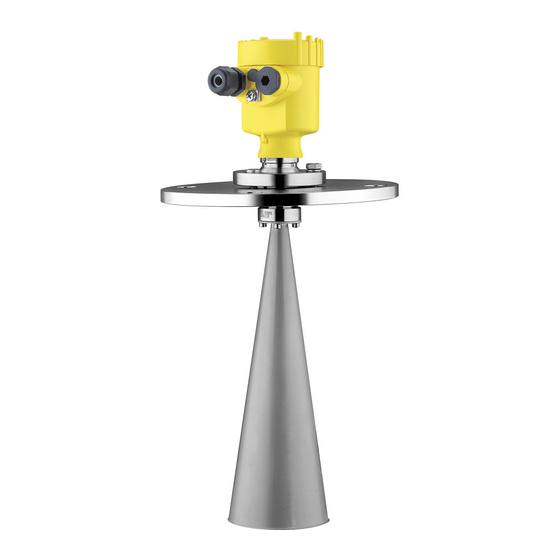
- Supplementary instructions manual "Plug connector for continuously measuring sensors" (optional) - Ex-specific "Safety instructions" (with Ex-versions) - if necessary, further certificates VEGAPULS 68 consists of the following components: Components Horn or parabolic antenna process fitting (depending on the version flange or thread) Optionally available with swivelling holder (only with flange), rinsing air connection, reflux valve... -
Page 10: Principle Of Operation
VEGAPULS 68 is a radar sensor in K-band technology for Area of application continuous level measurement in solids. A version of VEGAPULS 68 is available for each area of application: The version with horn antenna is particularly suitable for measurement of virtually all bulk solids in small silos and vessels. -
Page 11: Operation
A CD with the appropriate files and certificates can be ordered via e-mail under info@de.vega.com or by phone from one of the VEGA agencies under the order number "DRIVER.S". The backlight of the indicating and adjustment module is powered by the sensor. -
Page 12: Packaging, Transport And Storage
Not exposed to corrosive media Protected against solar radiation Avoiding mechanical shock and vibration Storage and transport temperature see "Supplement - Storage and transport tem- perature Technical data - Ambient conditions" Relative humidity 20 … 85 % VEGAPULS 68 - Foundation Fieldbus... -
Page 13: Mounting
Use the recommended cables (see chapter "Connecting to Moisture power supply") and tighten the cable gland. You can give your VEGAPULS 68 additional protection against moisture penetration by leading the connection cable down- ward in front of the cable entry. Rain and condensation water can thus drain off. -
Page 14: Mounting Preparations - Horn Antenna
4.2 Mounting preparations - Horn antenna Information: This information applies only to special versions! VEGAPULS 68 is also available in versions where the antenna has a bigger diameter than the process fitting (thread, flange). The antenna must therefore be disconnected from the process fitting before mounting. -
Page 15: Mounting Preparations - Parabolic Antenna
4.3 Mounting preparations - Parabolic antenna Information: This information applies only to special versions! Der VEGAPULS 68 is also available in versions where the antenna has a bigger diameter than the process fitting (thread, flange). The antenna must therefore be disconnected from the flange before mounting. - Page 16 Mounting 1 Clamp VEGAPULS 68 with flange, e.g. in a bench vice 2 Hold the connection piece (3) with a wrench SW 22 on the flattenings 3 Unscrew the locknut (2) with SW 36 against the antenna 4 Loosen compression nut (1) with a screwdriver SW 41...
-
Page 17: Mounting Instructions
4.4 Mounting instructions The illustrations to the following mounting instructions show Horn and parabolic antenna VEGAPULS 68 with horn antenna. The mounting instructions apply analogously also to VEGAPULS 68 with parabolic antenna. Mount the sensor at least 200 mm (7.874 in) away from the Installation position vessel wall. - Page 18 If mounting in the center of the silo is not possible, the sensor can be directed to the vessel center by means of an optional swivelling holder. The following description gives an overview on the determination of the necessary angle of inclination. VEGAPULS 68 - Foundation Fieldbus...
- Page 19 Mounting Fig. 8: Proposal for installation after orientation VEGAPULS 68 The angle of inclination depends on the vessel dimensions. It can be checked easily on the sensor with a suitable level or air-lever. The following chart states the distance "a" between installation position and vessel center depending on the measuring distance for an angle of inclination of 2°...
- Page 20 The optimum mounting position is on the opposite of the filling. To avoid strong pollution, the distance to the filter or dust extraction must be as big as possible. VEGAPULS 68 - Foundation Fieldbus...
- Page 21 Fig. 10: Recommended socket mounting If the reflective properties of the medium are good, you can mount VEGAPULS 68 on sockets which are higher than the length of the antenna. You will find recommended values for socket heights in the following illustration. The socket end should be smooth and burr-free, if possible also rounded.
- Page 22 150 mm/6" 800 mm Fig. 11: Deviating socket dimensions Tip: VEGAPULS 68 is optionally also available with antenna extension. Hence the antenna length can be selected such that the antenna end protrudes 10 mm (0.4 in) out of the socket.
- Page 23 Mounting Fig. 12: Installation of VEGAPULS 68 in multiple chamber silos Fig. 13: Orientation of VEGAPULS 68 for emptying in the silo center Silo installations such as e.g. ladders, level switches, struts, Vessel installations and also structured vessel walls, can cause false echoes that get superimposed on the useful echo.
- Page 24 Tip: In case of extreme dust in the antenna system, VEGAPULS 68 is available with purging connection e.g. for air. The air is distributed via channels in the antenna system and keeps is virtually clean from dust.
- Page 25 Keep in mind that for these applications, the sensors are designed for relatively slow level changes. When using VEGAPULS 68 on a movable bracket, the max. measuring rate must be observed (see chapter "Technical data"). VEGAPULS 68 - Foundation Fieldbus...
-
Page 26: Connecting To Power Supply
If overvoltage surges are expected, overvoltage arresters should be installed according to Foundation Fieldbus specification Tip: We recommend VEGA overvoltage arrester B63-32 In hazardous areas you should take note of the appropriate Take note of safety instructions for Ex regulations, conformity and type approval certificates of the applications sensors and power supply units. -
Page 27: Connection Steps - Instrument Housing
5 Insert the cable into the sensor through the cable entry 6 Lift the opening levers of the terminals with a screwdriver (see following illustration) 7 Insert the wire ends into the open terminals according to the wiring plan VEGAPULS 68 - Foundation Fieldbus... -
Page 28: Wiring Plan, Single Chamber Housing
12 Screw the housing cover on The electrical connection is finished. 5.3 Wiring plan, single chamber housing The following illustrations apply to the non-Ex as well as to the Ex-ia version. VEGAPULS 68 - Foundation Fieldbus... - Page 29 Plug connector for VEGACONNECT (I²C interface) Spring-loaded terminals for connection of the external indication VEGADIS Ground terminal for connection of the cable screen Spring-loaded terminals for Foundation Fieldbus connection Simulation switch ("on" = mode for simulation release) VEGAPULS 68 - Foundation Fieldbus...
-
Page 30: Wiring Plan, Double Chamber Housing
Ex-ia version. Housing overview Fig. 22: Double chamber housing Housing cover, connection compartment Blind stopper or plug M12 x 1 for VEGADIS 61 (optional) Housing cover, electronics compartment Filter element for air pressure compensation Cable gland VEGAPULS 68 - Foundation Fieldbus... - Page 31 Terminals for VEGADIS 61 Connection compartment I ² C Fig. 24: Connection compartment, double chamber housing Plug connector for VEGACONNECT (I²C interface) Ground terminal for connection of the cable screen Spring-loaded terminals for voltage supply VEGAPULS 68 - Foundation Fieldbus...
-
Page 32: Wiring Plan, Double Chamber Housing Exd
FM or CSA at a later date. Housing overview Fig. 26: Double chamber housing Housing cover, connection compartment Blind stopper or plug M12 x 1 for VEGADIS 61 (optional) Housing cover, electronics compartment Filter element for air pressure compensation Cable gland VEGAPULS 68 - Foundation Fieldbus... - Page 33 Connection for VEGACONNECT (I²C interface) Internal connection cable to the connection compartment Connection compartment Fig. 28: Connection compartment double chamber housing Ex d Spring-loaded terminals for power supply and cable screen Ground terminal for connection of the cable screen VEGAPULS 68 - Foundation Fieldbus...
-
Page 34: Wiring Plan - Version Ip 66/Ip 68, 1 Bar
(+) and blue (-) to power supply or to the processing system Screen 5.7 Switch on phase After VEGAPULS 68 is connected to voltage supply or after Switch on phase voltage recurrence, the instrument carries out a self-check for approx. -
Page 35: Set Up With The Indicating And Adjustment Module Plicscom
- each displaced by 90°) 3 Press the indicating and adjustment module onto the electronics and turn it to the right until it snaps in. 4 Screw housing cover with inspection window tightly back VEGAPULS 68 - Foundation Fieldbus... - Page 36 Fig. 31: Installation of the indicating and adjustment module Note: If you intend to retrofit the sensor with an indicating and adjustment module for continuous measured value indication, a higher cover with an inspection glass is required. VEGAPULS 68 - Foundation Fieldbus...
-
Page 37: Adjustment System
The functions of the individual keys are shown in the above illustration. Approx. 10 minutes after the last pressing of a key, an automatic reset to measured value indication is triggered. Any values not confirmed with [OK] will not be saved. VEGAPULS 68 - Foundation Fieldbus... -
Page 38: Setup Procedure
Set up with the indicating and adjustment module PLICSCOM 6.4 Setup procedure As VEGAPULS 68 is a distance measuring instrument, the Parameter adjustment distance from the sensor to the product surface is measured. To have the real product level displayed, an allocation of the measured distance to the percentage height must be made. - Page 39 "Solid" or "Liquid". Enter the requested parameter via the appropriate keys, save your settings and jump to the next menu item with the [->] key. VEGAPULS 68 - Foundation Fieldbus...
- Page 40 Information: However, the measuring signals are not damped by the product in completely empty, closed metal vessels. Due to this, considerable multiple reflections can be caused by which VEGAPULS 68 - Foundation Fieldbus...
- Page 41 The filling level would then no longer be detectable in this area. The menu item "Extended setting" offers the possibility to Extended setting/Quick level optimise VEGAPULS 68 for applications with quick level change changes. For this purpose select the function "Quick level change >1 m/min.".
- Page 42 Max. adjustment 15 m(d) (VEGAPULS 67) Min. adjustment 70 m(d) (VEGAPULS 68) Medium Solid Vessel form not known Damping Linearisation linear Sensor-TAG Sensor Displayed value AI-Out Extended settings None With standpipe versions. Sensor-specific basic adjustment. VEGAPULS 68 - Foundation Fieldbus...
- Page 43 You will find a detailed description of these menu items in the operating instructions manual "Indicating and adjustment module". Special parameters are parameters which are set customer-specifically on the service level with the adjustment software PACTware™. VEGAPULS 68 - Foundation Fieldbus...
-
Page 44: Menu Schematic
10.000 m(d) 0.000 m(d) 1.245 m(d) 6.789 m(d) Damping Linearisation curve linear Display Basic adjustment ▶ Display Diagnostics Service Info Displayed value Lighting ▼ AI-Out Switched off Diagnostics Basic adjustment Display ▶ Diagnostics Service Info VEGAPULS 68 - Foundation Fieldbus... - Page 45 Date of manufacture Last change using PC < max. 32 characters > VEGAPULS 6x 19. February 2007 Sensor-TAG (PD_TAG) Serial number Software version < max. 32 characters > 12345678 3.50 19. February 2007 Sensor characteristics Display now? VEGAPULS 68 - Foundation Fieldbus...
-
Page 46: Saving The Parameter Adjustment Data
They are hence available for multiple use or service purposes. If VEGAPULS 68 is equipped with an indicating and adjust- ment module, the most important data can be read out of the sensor into indicating and adjustment module. The procedure is described in the operating instructions manual "Indicating... -
Page 47: Setup With Pactware™ And Other Adjustment Programs
A detailed description is available in the online help of PACTware™ and the VEGA DTMs. Note: Keep in mind that for setup of VEGAPULS 68, DTM-Collection in the actual version must be used. VEGAPULS 68 - Foundation Fieldbus... -
Page 48: Parameter Adjustment With Ams
All currently available VEGA DTMs are provided in the DTM Collection on CD and can be obtained from the responsible VEGA agency for a token fee. This CD includes also the up-to- date PACTware™ version. The basic version of this DTM Collection incl. -
Page 49: Maintenance And Fault Rectification
Maintenance and fault rectification 8 Maintenance and fault rectification 8.1 Maintenance, cleaning When used as directed in normal operation, VEGAPULS 68 is completely maintenance free. In some applications, builup on the antenna system can influence the measuring result. Depending on the sensor and application, make arrangements to avoid strong pollution of the antenna system. - Page 50 Adjustment span too small à Carry out a fresh adjustment and increase the distance between min. and max. adjustment ? E036 no operable sensor software à Carry out a software update or send the instrument for repair VEGAPULS 68 - Foundation Fieldbus...
-
Page 51: Exchange Of The Electronics Module
Ex approval may be used. If there is no electronics module available on site, one can be ordered from the VEGA agency serving you. The order data of the sensor must be downloaded into the new Sensor serial number electronics module. -
Page 52: Instrument Repair
If a repair is necessary, please proceed as follows: You can download a return form (23 KB) from the Internet on our homepage www.vega.com under: "Downloads - Forms and certificates - Repair form". By doing this you help us carry out the repair quickly and without having to call for needed information. -
Page 53: Dismounting
Correct disposal avoids negative effects to persons and environment and ensures recycling of useful raw materials. Materials: see chapter "Technical data" If you cannot dispose of the instrument properly, please contact us about disposal methods or return. VEGAPULS 68 - Foundation Fieldbus... -
Page 54: Supplement
5 … 16.2 kg (11.02 … 35.71 lbs) - Process fitting - flange, depending on flange size and housing 6 … 17.2 kg (13.23 … 37.92 lbs) - Process fitting swivelling holder with flange, depending on flange size and housing VEGAPULS 68 - Foundation Fieldbus... - Page 55 1 s Interval Beam angle 3 dB with horn antenna, depending on antenna diameter - ø 40 mm (1.575 in) 22° - ø 48 mm (1.89 in) 18° - ø 75 mm (2.953 in) 10° VEGAPULS 68 - Foundation Fieldbus...
- Page 56 70 m -15 mm -30 mm Fig. 34: Deviation VEGAPULS 68 with horn antenna in mm, measuring range in m Time to output the correct level (with max. 10 % deviation) after a sudden level change. Incl. non-linearity, hysteresis and non-repeatability.
- Page 57 1.180 in 0.590 in 3.280 ft 229.7 ft - 0.590 in - 1.180 in Fig. 35: Deviation VEGAPULS 68 with horn antenna in Inch, measuring range in ft 40 mm 15 mm 2,0 m 70 m -15 mm -40 mm Fig.
- Page 58 4 g and 5 … 100 Hz Vibration resistance Data on rinsing air connection max. 6 bar (87.02 psi) Pressure Relating to the nominal measuring range. Tested according to the regulations of German Lloyd, GL directive 2. VEGAPULS 68 - Foundation Fieldbus...
- Page 59 Reflux valve - attached (with non-Ex option, with Ex in the scope of delivery) 316Ti - Material - Seal FKM (Viton), Kalrez 6 mm - for tube diameter 0.5 bar (7.25 psi) - opening pressure PN 250 - Nominal pressure stage VEGAPULS 68 - Foundation Fieldbus...
- Page 60 1 x IP 68 cable gland M20 x 1.5; 1 x blind - Double chamber housing stopper M20 x 1.5; 1 x blind stopper M16 x 1.5 Depending on the version M12 x 1, according to DIN 43650, Harting, Am- phenol-Tuchel, 7/8" FF. VEGAPULS 68 - Foundation Fieldbus...
- Page 61 Supply voltage with lighted indicating and adjustment module 12 … 32 V DC - Non-Ex instrument 12 … 24 V DC - EEx-ia instrument Power supply by/max. number of sensors max. 32 (max. 10 with Ex) - H1 power supply VEGAPULS 68 - Foundation Fieldbus...
- Page 62 (XP-IS) CL I, II, III, DIV1, GP ABCDEFG Ship approvals GL, LRS, ABS, CCS, RINA A suitable cable is the prerequisite for maintaining the protection class. Deviating data in Ex applications: see separate safety instructions. Depending on order specification. VEGAPULS 68 - Foundation Fieldbus...
-
Page 63: Foundation Fieldbus
Channel = 1: Primary Value AI 2 Channel = 2: Secondary Value 1 Channel = 3: Secondary Value 2 Fig. 39: VEGAPULS 68 measured value processing Diagram, adjustment The following illustration shows the function of the adjustment. VEGAPULS 68 - Foundation Fieldbus... - Page 64 Calibration Highest Point cal_level_lo [%] Calibration Lowest Point Fig. 40: Adjustment VEGAPULS 68 Parameter list The following list contains the most important parameters and their meaning: primary_value Process value after min/max-adjustment and linearization. Selected as input to AIFB by setting 'Channel' = 1. Unit derives from 'Primary_value_unit' primary_value_unit Selected unit code for "primary_value"...
- Page 65 Min./max.-adjustment: Upper calibrated point of the sensor. It refers to 'Cal_level_hi'. The unit is defined in 'Sensor_range.unit' Calibration Lowest Point Min./max.-adjustment: Lower calibrated point of the sensor. It refers to 'Cal_level_lo'. The unit is defined in 'Sensor_range.unit' cal_level_hi VEGAPULS 68 - Foundation Fieldbus...
- Page 66 Set up to suit the process conditions. If Special-Parameter adjustment has been utilized this parameter cannot be written fast_level_change Set up to suit the process conditions. If Special-Parameter adjustment has been utilized this parameter cannot be written VEGAPULS 68 - Foundation Fieldbus...
- Page 67 Signal/Noise ratio empty_vessel_curve_corr_dist Distance from the sensor to the product surface. Unit derives from 'Sensor_range.unit' empty_vessel_curve_corr_op_code Update, create new or delete the empty vessel curve tube diameter Set up to suit the process conditions VEGAPULS 68 - Foundation Fieldbus...
-
Page 68: Dimensions
") M16x1,5 M20x1,5 M20x1,5 M20x1,5 M20x1,5/ ½ NPT Fig. 42: Housing versions in protection IP 68 (with integrated PLICSCOM the housing is 9 mm/0.35 in higher) Stainless steel housing Aluminium double chamber housing Aluminium housing VEGAPULS 68 - Foundation Fieldbus... - Page 69 3" ø75 4" ø95 inch " ø1 " 1½" " ø1 " 2" " ø2 " 3" " ø3 " 4" Fig. 43: VEGAPULS 68 - horn antenna in threaded version Standard with temperature adapter VEGAPULS 68 - Foundation Fieldbus...
- Page 70 4" " ø3 " Fig. 44: VEGAPULS 68 - horn antenna in threaded version with purging air connection Standard with temperature adapter Purging air connection G⅛ A for mounting of a suitable adapter Reflux valve - attached (with non-Ex optionally available, with Ex in the scope of delivery), for tube diameters 6 mm...
- Page 71 " ø3 " 4" Fig. 45: VEGAPULS 68 - horn antenna in threaded version with antenna extension Standard with temperature adapter An antenna extension causes a reduction of sensitivity at close range in dependence on product properties. A suitable support for the antenna extension must be provided as required by its length.
- Page 72 4" 150 lb " " 6" 150 lb 279,4 25,4 241,3 8xø22,4 6" 150 lb 11" 1" " 8xø " " " Fig. 46: VEGAPULS 68 - horn antenna in flange version Standard with temperature adapter VEGAPULS 68 - Foundation Fieldbus...
- Page 73 " 8xø " " Fig. 47: VEGAPULS 68 - horn antenna in flange version with purging air connection Standard with temperature adapter Purging air connection G⅛ A for mounting of a suitable adapter Reflux valve - attached (with non-Ex optionally available, with Ex in the scope of delivery), for tube diameters 6 mm...
- Page 74 " " " 4xø " " " " 8xø " DN 100 / 4" 11,5 182,5 4xø22 DN 100 / 4" Fig. 48: VEGAPULS 68 - horn antenna and swivelling holder Standard with temperature adapter VEGAPULS 68 - Foundation Fieldbus...
- Page 75 8xø " Fig. 49: VEGAPULS 68 - horn antenna, swivelling holder and purging air connection Purging air connection G⅛ A for mounting of a suitable adapter Reflux valve - attached (with non-Ex optionally available, with Ex in the scope of delivery), for tube diameters 6 mm...
- Page 76 Supplement VEGAPULS 68 - parabolic antenna in threaded version 46mm ") G1½A / 1½ NPT ø 244mm (9 ") Fig. 50: VEGAPULS 68 - parabolic antenna in threaded version Standard with temperature adapter VEGAPULS 68 - Foundation Fieldbus...
- Page 77 4" 150 lb 9" " " 8xø " 6" 150 lb 279,4 25,4 241,3 8xø22,4 6" 150 lb 11" 1" " 8xø " Fig. 51: VEGAPULS 68 - parabolic antenna in flange version Standard with temperature adapter VEGAPULS 68 - Foundation Fieldbus...
- Page 78 " " " 4xø " " " " 8xø " DN 100 / 4" 11,5 182,5 4xø22 DN 100 / 4" Fig. 52: VEGAPULS 68 - parabolic antenna and swivelling holder Standard with temperature adapter VEGAPULS 68 - Foundation Fieldbus...
- Page 79 11,5 182,5 4xø22 DN 100 / 4" Fig. 53: VEGAPULS 68 - parabolic antenna and swivelling holder with purging air connection Standard with temperature adapter Purging air connection G⅛ A for mounting of a suitable adapter Reflux valve - attached (with non-Ex optionally available, with Ex in the scope of delivery), for tube diameters 6 mm...
- Page 80 Les lignes de produits VEGA sont globalement protégées par des droits de propriété intellectuelle. Pour plus d'informations, on pourra se référer au site http://www.vega.com. VEGA lineas de productos están protegidas por los derechos en el campo de la propiedad industrial. Para mayor información revise la pagina web http://www.vega.com.
- Page 81 Supplement VEGAPULS 68 - Foundation Fieldbus...
- Page 82 Supplement VEGAPULS 68 - Foundation Fieldbus...
- Page 83 Supplement VEGAPULS 68 - Foundation Fieldbus...
- Page 84 All statements concerning scope of delivery, application, practical use and operating conditions of the sensors and processing systems correspond to the information avail- able at the time of printing. © VEGA Grieshaber KG, Schiltach/Germany 2007 29264-EN-071112 Subject to change without prior notice...
Need help?
Do you have a question about the VEGAPULS 68 and is the answer not in the manual?
Questions and answers