
Related Manuals for Vega vegaplus sr 68


Summary of Contents for Vega vegaplus sr 68
-
Page 1: Operating Instructions
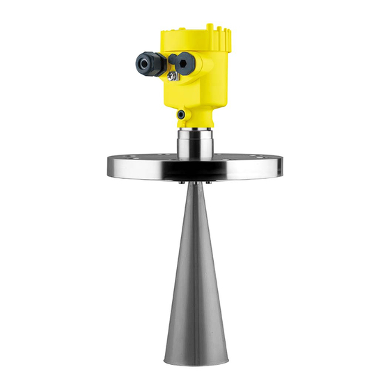
Operating Instructions Radar sensor for continuous level measurement of bulk solids VEGAPULS SR 68 4 … 20 mA/HART - two-wire Document ID: 38294... -
Page 2: Table Of Contents
Contents Contents About this document Function ........................... 4 Target group ........................4 Symbols used........................4 For your safety Authorised personnel ....................... 5 Appropriate use ........................ 5 Warning about incorrect use ..................... 5 General safety instructions ....................5 CE conformity ........................6 NAMUR recommendations .................... - Page 3 Contents Diagnosis, asset management and service Maintenance ........................60 Measured value and event memory ................60 Asset Management function ................... 61 Rectify faults ........................64 Exchanging the electronics module ................67 Software update ......................68 How to proceed if a repair is necessary ................68 10 Dismount 10.1 Dismounting steps......................
-
Page 4: About This Document
1 About this document About this document Function This operating instructions manual provides all the information you need for mounting, connection and setup as well as important instruc- tions for maintenance and fault rectification. Please read this informa- tion before putting the instrument into operation and keep this manual accessible in the immediate vicinity of the device. -
Page 5: For Your Safety
2 For your safety For your safety Authorised personnel All operations described in this operating instructions manual must be carried out only by trained specialist personnel authorised by the plant operator. During work on and with the device the required personal protective equipment must always be worn. -
Page 6: Ce Conformity
2 For your safety CE conformity The device fulfils the legal requirements of the applicable EC guide- lines. By affixing the CE marking, we confirm successful testing of the product. You can find the CE Certificate of Conformity in the download section of our homepage. Electromagnetic compatibility Instruments in four-wire or Ex-d-ia version are designed for use in an industrial environment. Nevertheless, electromagnetic interference from electrical conductors and radiated emissions must be taken into account, as is usual with class A instruments according to EN 61326- 1. If the instrument is used in a different environment, the electromag- netic compatibility to other instruments must be ensured by suitable... -
Page 7: Radio License For Usa/Canada
2 For your safety • The instrument must only be installed and maintained by appropri- ately qualified staff Radio license for USA/Canada The instrument is in conformity with part 15 of the FCC regulations. Take note of the following two regulations: • This device may not cause interference, and •... -
Page 8: Product Description
Alternatively, you can access the data via your smartphone: • Download the smartphone app "VEGA Tools" from the "Apple App Store" or the "Google Play Store" • Scan the Data Matrix code on the type label of the instrument or •... -
Page 9: Principle Of Operation
3 Product description This operating instructions manual applies to the following instrument Scope of this operating instructions manual versions: • Hardware version from 2.1.0 • Software version from 4.5.1 Scope of delivery The scope of delivery encompasses: • Radar sensor •... -
Page 10: Accessories And Replacement Parts
PACTware with VEGA-DTM is required. You can find further information in the operating instructions "Interface adapter VEGACONNECT" (Document-ID 32628). VEGADIS 81 The VEGADIS 81 is an external display and adjustment unit for VEGA plics sensors. ® For sensors with double chamber housing the interface adapter "DISADAPT"... - Page 11 3 Product description You can find further information in the operating instructions "VE- GADIS 82 4 … 20 mA/HART" (Document-ID 45300). PLICSMOBILE T61 PLICSMOBILE T61 is an external GSM/GPRS radio unit for transmis- sion of measured values and for remote parameter adjustment of plics sensors. Adjustment is carried out via PACTware/DTM and the ®...
-
Page 12: Mounting
4 Mounting Mounting General instructions Screwing in On instruments with threaded process fitting, the hexagon must be tightened with a suitable wrench. For the proper wrench size see chapter "Dimensions". Warning: The housing must not be used to screw the instrument in! Applying tightening force can damage internal parts of the housing. Protection against mois- Protect your instrument against moisture ingress through the following ture measures: •... -
Page 13: Mounting Preparations
4 Mounting Prior to setup you have to replace these protective caps with ap- proved cable glands or close the openings with suitable blind plugs. Mounting preparations The instrument is also available in versions with an antenna whose diameter is larger than the process fitting (thread, flange). In such cases the antenna must be disconnected from the process fitting before mounting. - Page 14 4 Mounting spring rings according to DIN 217 or wedge lock washers according to DIN 25 201. Parabolic antenna Proceed as follows: 1. Clamp VEGAPULS SR 68 with the flange, e.g. in a bench vice 2. Hold the connection piece (1) with a wrench on the flat surfaces (width across flats 22 mm) 3. Loosen counter nut (3) completely with a wrench (width across flats 36 mm) in the direction of the antenna 4. Loosen compression nut (2) completely with a wrench (width across flats 41 mm) in the direction of the antenna 5.
-
Page 15: Mounting Instructions
4 Mounting Mounting instructions Polarisation The emitted radar impulses of the radar sensor are electromagnetic waves. The polarisation is the direction of the electrical wave compo- nent. By turning the instrument in the connection flange or mounting boss, the polarisation can be used to reduce the effects of false echoes. The position of the polarisation is marked on the process fitting of the instrument. Fig. 4: Position of the polarisation Marking with screwed version 2 Marking with flange version Installation position Mount the sensor at least 200 mm (7.874 in) away from the vessel... - Page 16 4 Mounting Fig. 6: Mounting of the radar sensor with inflowing medium With bulk solids silos with lateral pneumatic filling, mounting should not be in the filling stream as the microwave signal will be interferred. The optimum mounting position is next to the filling. To avoid strong pollution, the distance to the filter or dust extraction must be as big as possible. VEGAPULS SR 68 • 4 … 20 mA/HART - two-wire...
- Page 17 4 Mounting Fig. 7: Mounting of the radar sensor with inflowing medium Mounting socket The socket piece should be dimensioned in such a way that the antenna end protrudes slightly out of the socket. VEGAPULS SR 68 • 4 … 20 mA/HART - two-wire...
- Page 18 4 Mounting Fig. 8: Recommended socket mounting with horn antenna Fig. 9: Recommended socket mounting with parabolic antenna When using a swivelling holder, keep in mind that the distance between antenna and socket gets smaller as the inclination of the sensor increases. Additional false reflections may be generated which can influence the measuring result at close range. Max. torque see chapter "Technical data"...
- Page 19 4 Mounting Fig. 11: Distance between antenna and socket with parabolic antenna If the medium has good reflective properties, VEGAPULS SR 68 with horn antenna can also be mounted on a longer socket piece. Recommended values for socket heights are specified in the following illustration. You must carry out a false signal suppression afterwards. Fig. 12: Deviating socket dimensions Socket diameter d Socket length h Recommended anten-...
- Page 20 4 Mounting required minimum distance, especially with poorly reflecting media such as plastic powder. In practice, a cleanly constructed mounting socket, if necessary with rounded edges, introduces fewer disturbing influences than an antenna extension. Orientation To measure as much of the vessel volume as possible, the sensor should be aligned so that the measuring beam reaches the lowest level in the vessel.
- Page 21 4 Mounting Fig. 14: Proposal for installation after orientation VEGAPULS SR 68 The angle of inclination depends on the vessel dimensions. It can be easily checked with a suitable level or water leve on the sensor. The following table specifies the distance "a" between installation position and vessel centre dependent on the measuring distance for inclination angles of 2°...
- Page 22 4 Mounting To adjust the angle of inclination with the swivelling holder see next section. Swivelling holder Proceed as follows to align the sensor with the swivelling holder: 1. Loosen terminal screw of the swivelling holder with a fork spanner SW 13 Fig.
- Page 23 4 Mounting If there are agitators in the vessel, a false signal suppression should Agitators be carried out with the agitators in motion. This ensures that the interfering reflections from the agitators are saved with the blades in different positions. Fig. 17: Agitators Material heaps Large material heaps are detected with several sensors, which can be mounted on e.g.
- Page 24 4 Mounting Information: The spacer may only be incorporated up to a maximum of 50 mm into the vessel insulation. Only then is a reliable temperature decoupling guaranteed. Fig. 19: Mounting the instrument on insulated vessels. Electronics housing Spacer Vessel insulation Installation in subsurface For level measurements in concrete silos, the sensors are often enclosures...
- Page 25 4 Mounting The silo walls of multiple chamber silos are often made of profile Mounting in multiple chamber silo walls, such as e.g. profile sheeting, to ensure the required stability. If the radar sensor is mounted very close to a heavily structured vessel wall, considerable false reflections can be generated. Hence the sen- sor should be mounted at a large distance from the separating wall. The optimal mounting position is on the outer wall of the silo with the sensor directed towards the emptying aperture in the silo center.
- Page 26 4 Mounting To avoid strong buildup and dust in the antenna system, the sensor Dust deposits should not be mounted directly at the dust extraction of the vessel. In case of extreme dust deposits in the antenna system, VEGAPULS SR 68 is available with a rinsing air connection. The air is distributed via channels in the antenna system and keeps it largely free of dust.
-
Page 27: Connecting To Power Supply
5 Connecting to power supply Connecting to power supply Preparing the connection Safety instructions Always keep in mind the following safety instructions: Warning: Connect only in the complete absence of line voltage. • The electrical connection must only be carried out by trained personnel authorised by the plant operator. -
Page 28: Connecting
5 Connecting to power supply Prior to setup you have to replace these protective caps with ap- proved cable glands or close the openings with suitable blind plugs. With plastic housing, the NPT cable gland or the Conduit steel tube must be screwed without grease into the threaded insert. - Page 29 5 Connecting to power supply Fig. 25: Connection steps 5 and 6 - Single chamber housing Fig. 26: Connection steps 5 and 6 - Double chamber housing 6. Insert the wire ends into the terminals according to the wiring plan Information: Solid cores as well as flexible cores with wire end sleeves are insert- ed directly into the terminal openings. In case of flexible cores without...
-
Page 30: Wiring Plan, Single Chamber Housing
5 Connecting to power supply 9. Tighten the compression nut of the cable entry gland. The seal ring must completely encircle the cable 10. Reinsert the display and adjustment module, if one was installed 11. Screw the housing lid back on The electrical connection is finished. - Page 31 5 Connecting to power supply Terminal compartment 4...20mA Display 6 7 8 Fig. 29: Terminal compartment, double chamber housing Voltage supply, signal output For display and adjustment module or interface adapter For external display and adjustment unit Ground terminal for connection of the cable screen Information: Parallel use of an external display and adjustment unit and a display and adjustment module in the terminal compartment is not supported.
-
Page 32: Wiring Plan, Double Chamber Housing Ex D Ia
5 Connecting to power supply Wiring plan, double chamber housing Ex d ia Electronics compartment 4...20mA 6 7 8 Fig. 31: Electronics compartment, double chamber housing Ex d ia Internal connection to the terminal compartment For display and adjustment module or interface adapter Internal connection to the plug connector for external display and adjust- ment unit (optional) Note:... -
Page 33: Double Chamber Housing With Dis-Adapt
5 Connecting to power supply Contact pin Colour connection ca- Terminal, electronics ble in the sensor module Pin 1 Brown Pin 2 White Pin 3 Blue Pin 4 Black Double chamber housing with DIS-ADAPT Electronics compartment Fig. 34: View to the electronics compartment with DISADAPT for connection of the external display and adjustment unit DISADAPT Internal plug connection... -
Page 34: Wiring Plan - Version Ip 66/Ip 68, 1 Bar
5 Connecting to power supply Wiring plan - version IP 66/IP 68, 1 bar Wire assignment, con- nection cable Fig. 36: Wire assignment in permanently connected connection cable brown (+) and blue (-) to power supply or to the processing system Shielding Switch-on phase After connecting the instrument to power supply or after a voltage... -
Page 35: Set Up With The Display And Adjustment Module
6 Set up with the display and adjustment module Set up with the display and adjustment module Insert display and adjustment module The display and adjustment module can be inserted into the sensor and removed again at any time. You can choose any one of four differ- ent positions - each displaced by 90°. It is not necessary to interrupt the power supply. -
Page 36: Adjustment System
6 Set up with the display and adjustment module Fig. 38: Installing the display and adjustment module in the double chamber housing In the electronics compartment In the terminal compartment Note: If you intend to retrofit the instrument with a display and adjustment module for continuous measured value indication, a higher lid with an inspection glass is required. -
Page 37: Measured Value Indication - Selection National Language
6 Set up with the display and adjustment module – Move to the menu overview – Confirm selected menu – Edit parameter – Save value • [->] key: – Change measured value presentation – Select list entry – Select menu items in the quick setup menu –... -
Page 38: Parameter Adjustment
6 Set up with the display and adjustment module This menu item is used to select the national language for further pa- Selection of national language rameter adjustment. You can change the selection via the menu item "Setup - Display, Menu language". With the "OK"... - Page 39 6 Set up with the display and adjustment module nation must be entered for exact identification of individual measuring points. The available digits comprise: • Letters from A … Z • Numbers from 0 … 9 • Special characters +, -, /, - Each medium has different reflection properties. With liquids, further Setup - Medium interfering factors are fluctuation product surface and foam genera- tion. With bulk solids, these are dust generation, material cone and additional echoes from the vessel wall.
- Page 40 6 Set up with the display and adjustment module The selection "Standpipe" opens a new window in which the inner diameter of the applied standpipe is entered. The following features form the basis of the applications: Storage tank: • Setup: large-volumed, upright cylindrical, spherical •...
- Page 41 6 Set up with the display and adjustment module – High accuracy – False signal suppression required Stirrer vessel (reactor): • Setup: all vessel sizes possible • Medium speed: – Fast to slow filling possible – Vessel is filled and emptied very often • Vessel: – Socket available – Large agitator blades of metal –...
- Page 42 6 Set up with the display and adjustment module • Vessel: – Lateral outlets and inlets – Joins like flanges, weld joints – Shifting of the running time in the tube • Process/measurement conditions: – Condensation – Buildup – Separation of oil and water possible –...
- Page 43 6 Set up with the display and adjustment module – Insensitive in the close range Open flume (flow measurement): • Rate of level change: slow level change • Process/measurement conditions: – Ice and condensation on the antenna possible – Spiders and insects build nests in the antennas –...
- Page 44 6 Set up with the display and adjustment module Enter the requested parameters via the appropriate keys, save your settings with [OK] and jump to the next menu item with the [ESC] and the [->] key. Through this selection the operating range of the sensor is adapted Setup - Vessel height, measuring range to the vessel height, which considerably increases measurement...
- Page 45 6 Set up with the display and adjustment module tions is always the sealing surface of the thread or flange. You can find specifications on the reference plane in chapter "Technical data". The actual level is calculated on the basis of these settings. The actual product level during this adjustment is not important, because the min./max. adjustment is always carried out without changing the product level.
- Page 46 6 Set up with the display and adjustment module 3. Set the requested percentage value with [+] and save with [OK]. The cursor jumps now to the distance value. 4. Enter the appropriate distance value in m (corresponding to the percentage value) for the full vessel.
- Page 47 6 Set up with the display and adjustment module In this menu item, the PIN is activated/deactivated permanently. Lock setup - adjustment Entering a 4-digit PIN protects the sensor data against unauthorized access and unintentional modifications. If the PIN is activated perma- nently, it can be deactivated temporarily (i.e. for approx. 60 min.) in any menu item. Only the following functions are permitted with activated PIN: •...
- Page 48 6 Set up with the display and adjustment module In delivery status, the lighting is switched on. Diagnostics - Device In this menu item, the device status is displayed. status Diagnosis - Peak value The respective min. and max. measured value is saved in the sensor. The values are displayed in the menu item "Peak values".
- Page 49 6 Set up with the display and adjustment module How to start the simulation: 1. Push [OK] 2. Select the requested simulation variable with [->] and confirm with [OK]. 3. With [OK] you start the simulation, first of all the actual measured value is displayed in % 4. Start the editing mode with [OK] 5.
- Page 50 6 Set up with the display and adjustment module The function "Echo curve memory" makes it possible to save the echo Diagnostics - Echo curve memory curve at the time of setup. This is generally recommended, and it is absolutely necessary to do this if you want to use the Asset Manage- ment functions.
- Page 51 6 Set up with the display and adjustment module 4. Confirm again with [OK] and enter the actual distance from the sensor to the product surface. 5. All interfering signals in this section are detected by the sensor and stored after confirming with [OK]. Note: Check the distance to the product surface, because if an incorrect (too large) value is entered, the existing level will be saved as a false signal.
- Page 52 6 Set up with the display and adjustment module Enter the requested parameters via the appropriate keys, save your settings and jump to the next menu item with the [ESC] and [->] key. Caution: Note the following if instruments with appropriate approval are used as part of an overfill protection system according to WHG: If a linearisation curve is selected, the measuring signal is no longer necessarily linear to the filling height. This must be considered by the...
- Page 53 6 Set up with the display and adjustment module value memory as well as event memory remain untouched. The linearisation is set to linear. False signal suppression: Deleting a previously created false signal suppression. The false signal suppression created in the factory remains active.
- Page 54 6 Set up with the display and adjustment module The sensor offers the HART modes standard and Multidrop. In this Additional adjustments - HART mode menu item you specify the HART mode and enter the address for Multidrop. The mode "standard" with the fixed address 0 means outputting the measured value as a 4 … 20 mA signal. In Multidrop mode, up to 63 sensors can be operated on one two-wire cable.
-
Page 55: Saving The Parameter Adjustment Data
6 Set up with the display and adjustment module Info - Instrument version In this menu item, the hardware and software version of the sensor is displayed. Info - Date of manufacture In this menu item, the date of factory calibration of the sensor as well as the date of the last change of sensor parameters are displayed via the display and adjustment module or via the PC. -
Page 56: Setup With Pactware
Interface adapter, for example VEGACONNECT 4 Note: With power supply units with integrated HART resistance (internal resistance approx. 250 Ω), an additional external resistance is not necessary. This applies, e.g. to the VEGA instruments VEGATRENN 149A, VEGAMET 381, VEGAMET 391. Common Ex separators are VEGAPULS SR 68 • 4 … 20 mA/HART - two-wire... -
Page 57: Parameter Adjustment
7 Setup with PACTware also usually equipped with a sufficient current limiting resistance. In such cases, the interface converter can be connected parallel to the 4 … 20 mA cable (dashed line in the previous illustration). Parameter adjustment Prerequisites For parameter adjustment of the instrument via a Windows PC, the configuration software PACTware and a suitable instrument driver (DTM) according to FDT standard are required. -
Page 58: Saving The Parameter Adjustment Data
The standard version is available as a download under www.vega.com/downloads and "Software". The full version is avail- able on CD from the agency serving you. Saving the parameter adjustment data We recommend documenting or saving the parameter adjustment data via PACTware. -
Page 59: Set Up With Other Systems
DD adjustment programs Device descriptions as Enhanced Device Description (EDD) are available for DD adjustment programs such as, for example, AMS™ and PDM. The files can be downloaded at www.vega.com/downloads under "Software". Field Communicator 375, 475 Device descriptions for the instrument are available as EDD for pa- rameter adjustment with the Field Communicator 375 or 475. -
Page 60: Diagnosis, Asset Management And Service
9 Diagnosis, asset management and service Diagnosis, asset management and service Maintenance If the instrument is used correctly, no maintenance is required in normal operation. In some applications, buildup on the antenna system can influence the measuring result. Depending on the sensor and application, take measures to avoid heavy soiling of the antenna system. If necessary, clean the antenna system in certain intervals. -
Page 61: Asset Management Function
9 Diagnosis, asset management and service • PC with PACTware/DTM • Control system with EDD • Display and adjustment module Further echo curves: Up to 10 echo curves can be stored in a ring buffer in this memory section. Further echo curves are stored via: • PC with PACTware/DTM • Control system with EDD Asset Management function The instrument features self-monitoring and diagnostics according to... - Page 62 9 Diagnosis, asset management and service still valid. Plan in maintenance for the instrument because a failure is expected in the near future (e.g. due to buildup). This status message is inactive by default. It can be activated by the user via PACTware/DTM or EDD.
- Page 63 9 Diagnosis, asset management and service Code Cause Rectification DevSpec State in CMD Text message F125 – Temperature of the – Check ambient tem- Bit 7 of Byte 0…5 electronics in the non- perature Impermissible electronics specified range – Isolate electronics temperature –...
-
Page 64: Rectify Faults
9 Diagnosis, asset management and service Code Cause Rectification DevSpec State in CMD Text message S601 – Danger of vessel – Make sure that there is Bit 6 of Byte 14…24 overfilling no further filling Overfilling – Check level in the vessel Maintenance The following table shows the error codes and text messages in the status message "Maintenance"... - Page 65 9 Diagnosis, asset management and service • Checking the output signal • Treatment of measurement errors Further comprehensive diagnostics options are available with a PC with PACTware and the suitable DTM. In many cases, the reasons can be determined in this way and faults rectified. Connect a multimeter in the suitable measuring range according to Check the 4 …...
- Page 66 9 Diagnosis, asset management and service Measurement error with constant level Fault description Error pattern Cause Rectification 1. Measured value – Min./max. adjustment not – Adapt min./max. adjustment shows a too low or too correct high level – Incorrect linearization curve – Adapt linearization curve time 2.
-
Page 67: Exchanging The Electronics Module
24 hour service hotline Should these measures not be successful, please call in urgent cases the VEGA service hotline under the phone no. +49 1805 858550. The hotline is also available outside normal working hours, seven days a week around the clock. -
Page 68: Software Update
Interface adapter VEGACONNECT • PC with PACTware • Current instrument software as file You can find the current instrument software as well as detailed information on the procedure in the download area of our homepage: www.vega.com. Caution: Instruments with approvals can be bound to certain software versions. Therefore make sure that the approval is still effective after a software update is carried out. You can find detailed information in the download area at www.vega.com. - Page 69 9 Diagnosis, asset management and service • Please contact the agency serving you to get the address for the return shipment. You can find the agency on our home page www.vega.com. VEGAPULS SR 68 • 4 … 20 mA/HART - two-wire...
-
Page 70: Dismount
10 Dismount 10 Dismount 10.1 Dismounting steps Warning: Before dismounting, be aware of dangerous process conditions such as e.g. pressure in the vessel or pipeline, high temperatures, cor- rosive or toxic products etc. Take note of chapters "Mounting" and "Connecting to power supply" and carry out the listed steps in reverse order. -
Page 71: Supplement
11 Supplement 11 Supplement 11.1 Technical data Note for approved instruments The technical data in the respective safety instructions are valid for approved instruments (e.g. with Ex approval). These data can differ from the data listed herein, for example regarding the process conditions or the voltage supply. General data 316L corresponds to 1.4404 or 1.4435 Materials, wetted parts Ʋ... - Page 72 11 Supplement Ʋ Terminal screws, swivelling holder 15 Nm (11.06 lbf ft) Max. torques for NPT cable glands and Conduit tubes Ʋ Plastic housing 10 Nm (7.376 lbf ft) Ʋ Aluminium/Stainless steel housing 50 Nm (36.88 lbf ft) Input variable Measured variable The measured quantity is the distance between the end of the sensor antenna and the product surface.
- Page 73 11 Supplement Signal resolution 0.3 µA Resolution, digital < 1 mm (0.039 in) Failure signal current output (adjustable) mA-value unchanged 20.5 mA, 22 mA, < 3.6 mA Max. output current 22 mA Starting current ≤ 3.6 mA; ≤ 10 mA for 5 ms after switching on Load see load diagram under Power supply Damping (63 % of the input variable), 0 …...
- Page 74 11 Supplement Repeatability ≤ ±1 mm Deviation with bulk solids The values depend to a great extent on the application. Binding specifications are thus not possible. Deviation under EMC influence ≤ ±30 mm Variables influencing measurement accuracy Specifications apply to the digital measured value Temperature drift - Digital output ±3 mm/10 K, max. 10 mm Additional deviation through electromag- < ±50 mm netic interference acc. to EN 61326 Specifications apply also to the current output Temperature drift - Current output ±0.03 %/10 K relating to the 16 mA span max. ±0.3 %...
- Page 75 11 Supplement Process conditions For the process conditions, please also note the specifications on the type label. The lowest value always applies. Seal Antenna impedance Process temperature (measured on the process cone fitting) FKM (SHS FPM 70C3 PTFE -40 … +130 °C (-40 … +266 °F) GLT) FFKM (Kalrez 6375) PFFE -20 … +130 °C (-4 … +266 °F) PEEK -20 …...
- Page 76 11 Supplement Pressure Without reflux valve With reflux valve 1.5 bar (21.76 psig) 5.0 m 3.2 m 2 bar (29.0 psig) 5.5 m 4.5 m Air volume with parabolic antenna, depending on pressure (recommended area) Pressure Without reflux valve With reflux valve 0.5 bar (7.25 psig) 3.0 m 1.2 m 0.6 bar (8.70 psig) 3.2 m...
- Page 77 11 Supplement Wire cross-section (spring-loaded terminals) Ʋ Massive wire, stranded wire 0.2 … 2.5 mm² (AWG 24 … 14) Ʋ Stranded wire with end sleeve 0.2 … 1.5 mm² (AWG 24 … 16) Electromechanical data - version IP 66/IP 68 (1 bar) Options of the cable entry Ʋ...
- Page 78 11 Supplement Integrated clock Date format Day.Month.Year Time format 12 h/24 h Time zone Ex factory Rate deviation max. 10.5 min/year Additional output parameter - Electronics temperature Output of the temperature values Ʋ Analogue Via the current output Ʋ Digital Via the digital output signal - depending on the electron- ics version Range -40 …...
-
Page 79: Dimensions
Instruments with approvals can have different technical specifications depending on the version. For that reason the associated approval documents of these instruments have to be carefully noted. They are part of the delivery or can be downloaded under www.vega.com, "VEGA Tools" and "Instrument search" as well as in the download area. - Page 80 11 Supplement Aluminium housing ~ 116 mm ~ 87 mm (3.43") (4.57") ø 86 mm ø 86 mm (3.39") (3.39") M16x1,5 M20x1,5 M20x1,5/ ½ NPT M20x1,5/ ½ NPT Fig. 57: Housing versions with protection rating IP 66/IP 68 (0.2 bar) - with integrated display and adjustment module the housing is 9 mm/0.35 in higher Single chamber version Double chamber version...
- Page 81 11 Supplement Stainless steel housing ~ 69 mm ~ 87 mm ~ 59 mm (2.72") (3.43") (2.32") ø 86 mm ø 80 mm ø 79 mm (3.39") (3.15") (3.11") M16x1,5 M20x1,5/ ½ NPT M20x1,5/ M20x1,5/ ½ NPT ½ NPT Fig. 59: Housing versions with protection rating IP 66/IP 68 (0.2 bar) - with integrated display and adjustment module the housing is 9 mm/0.35 in higher Single chamber version, electropolished Single chamber version, precision casting...
- Page 82 11 Supplement VEGAPULS SR 68, horn antenna in threaded version SW 46 mm (1.81") G1½A / 1½ NPT 1½" ø40 2" ø48 3" ø75 4" ø95 inch 3.94" ø1.58" 1½" 4.72" ø1.89" 2" 8.50" ø2.95" 3" 16.93" ø3.74" 4" Fig. 61: VEGAPULS SR 68, horn antenna in threaded version Standard With temperature adapter up to 250 °C VEGAPULS SR 68 •...
- Page 83 11 Supplement VEGAPULS SR 68, horn antenna in flange version inch 3.94" ø1.58" 1½" ø40 1½" 4.72" ø1.89" 2" ø48 2" 8.50" ø2.95" 3" ø75 3" 16.93" ø3.74" 4" ø95 4" Fig. 62: VEGAPULS SR 68, horn antenna in flange version Standard With temperature adapter up to 250 °C VEGAPULS SR 68 • 4 … 20 mA/HART - two-wire...
- Page 84 11 Supplement VEGAPULS SR 68, horn antenna and swivelling holder 1½" ø 40 2" ø 48 3" ø 75 4" ø 95 inch 1½" 3.94" ø 1.58" 2" 4.72" ø 1.89" 8.50" ø 2.95" 3" 4" 16.93" ø 3.74" Fig. 63: VEGAPULS SR 68, horn antenna and swivelling holder Standard With temperature adapter up to 250 °C VEGAPULS SR 68 •...
- Page 85 11 Supplement VEGAPULS SR 68, parabolic antenna and swivelling holder Fig. 64: VEGAPULS SR 68, parabolic antenna and swivelling holder Standard With temperature adapter up to 200 °C VEGAPULS SR 68 • 4 … 20 mA/HART - two-wire...
-
Page 86: Industrial Property Rights
Les lignes de produits VEGA sont globalement protégées par des droits de propriété intellec- tuelle. Pour plus d'informations, on pourra se référer au site www.vega.com. VEGA lineas de productos están protegidas por los derechos en el campo de la propiedad indus- trial. Para mayor información revise la pagina web www.vega.com. - Page 87 INDEX INDEX Adjustment 37, 45 Main menu 38 Agitator 23 Meas. certainty 48 Measured value memory 60 Measurement loop name 38 Backlight 47 Mounting socket 17 Check output signal 65 NAMUR NE 107 61, 62, 64 Connection – Cable 27 Copy instrument settings 54 Overfill protection according to WHG 52 Current output Min./Max.
- Page 88 Subject to change without prior notice © VEGA Grieshaber KG, Schiltach/Germany 2016 VEGA Grieshaber KG Phone +49 7836 50-0 Am Hohenstein 113...
Need help?
Do you have a question about the vegaplus sr 68 and is the answer not in the manual?
Questions and answers