Vega VEGAPULS 68 Operating Instructions Manual
Profibus pa, sensor for continuous level measurement of bulk solids under simple process conditions, suitable for steel industry applications
Hide thumbs
Also See for VEGAPULS 68:
- Operating instructions manual (105 pages) ,
- Quick setup manual (24 pages) ,
- Product information (20 pages)
Table of Contents
Advertisement
Quick Links
Advertisement
Table of Contents

Subscribe to Our Youtube Channel
Related Manuals for Vega VEGAPULS 68


Summary of Contents for Vega VEGAPULS 68
-
Page 1: Operating Instructions
Operating Instructions VEGAPULS 68 Profibus PA Document ID: 29263... -
Page 2: Table Of Contents
6.10 Saving the parameter adjustment data ................43 Set up with PACTware and other adjustment programs Connect the PC ......................44 Parameter adjustment with PACTware ................45 Parameter adjustment with PDM ..................46 Saving the parameter adjustment data ................46 VEGAPULS 68 • Profibus PA... - Page 3 43814 - Externe Anzeige VEGADIS 81 • 34296 - Protective cover • 31088 - Flanges according to DIN-EN-ASME-JIS • 30176 - Electronics module VEGAPULS series 60 • 31381 - Antenna impedance cone VEGAPULS 62 and 68 Editing status: 2014-12-08 VEGAPULS 68 • Profibus PA...
-
Page 4: About This Document
Action This arrow indicates a single action. Sequence of actions Numbers set in front indicate successive steps in a procedure. Battery disposal This symbol indicates special information about the disposal of bat- teries and accumulators. VEGAPULS 68 • Profibus PA... -
Page 5: For Your Safety
During work on and with the device the required personal protective equipment must always be worn. Appropriate use VEGAPULS 68 is a sensor for continuous level measurement. You can find detailed information about the area of application in chapter "Product description". -
Page 6: Ce Conformity
IC: 3892A-PS68 Modifications not expressly approved by VEGA will lead to expiry of the operating licence according to FCC. VEGAPULS 68 is in conformity with part 15 of the FCC regulations. Take note of the respective operating regulations: • The instrument must not cause any interfering emissions •... - Page 7 2 For your safety • Chapter "Packaging, transport and storage" • Chapter "Disposal" VEGAPULS 68 • Profibus PA...
-
Page 8: Product Description
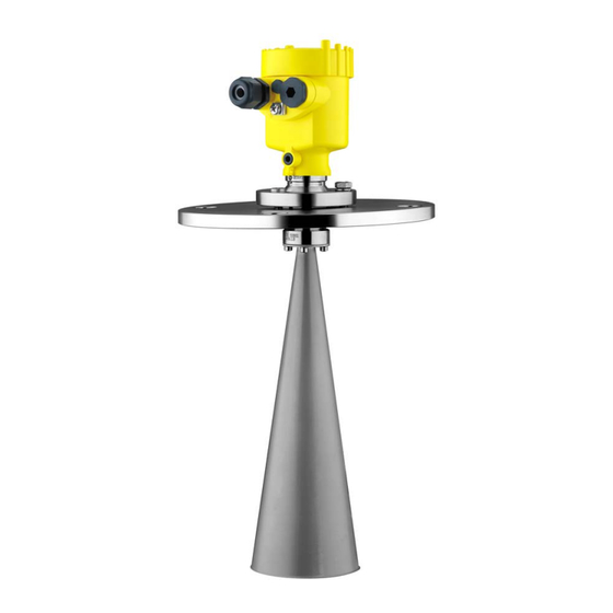
(optional) – Supplementary instructions manual "Plug connector for con- tinuously measuring sensors" (optional) – Ex-specific "Safety instructions" (with Ex versions) – if necessary, further certificates The VEGAPULS 68 consists of the components: Constituent parts • Horn or parabolic antenna •... - Page 9 3 Product description Fig. 1: VEGAPULS 68 - horn antenna and swivelling holder Housing cover with integrated PLICSCOM (optional) Housing with electronics 3 Swivelling holder with flange Horn antenna Type label The type label contains the most important data for identification and use of the instrument: •...
-
Page 10: Principle Of Operation
Area of application VEGAPULS 68 is a radar sensor in K-band technology for continuous level measurement of solids. A version of VEGAPULS 68 is available for each area of application. • The version with horn antenna is particularly suitable for measure- ment of virtually all bulk solids in small silos and vessels. -
Page 11: Packaging, Transport And Storage
Protected against solar radiation • Avoiding mechanical shock and vibration • Storage and transport temperature see chapter "Supplement - Storage and transport temperature Technical data - Ambient conditions" • Relative humidity 20 … 85 % VEGAPULS 68 • Profibus PA... -
Page 12: Mounting
Fig. 2: Measures against moisture ingress Measuring range The reference plane for the measuring range of the sensors is the lower edge of the flange or the seal surface of the thread. VEGAPULS 68 • Profibus PA... - Page 13 If the medium reaches the antenna, buildup can form on it and cause faulty measurements later on. Polarisation The emitted radar pulses of VEGAPULS 68 are electromagnetic waves. They thus have electrical and magnetical components that are perpendicular to each other. The polariation is defined by the direction of the electrical component.
-
Page 14: Mounting Preparations - Horn Antenna
Information: This information applies only to special versions! VEGAPULS 68 is also available in versions where the antenna has a bigger diameter than the process fitting (thread, flange). The antenna must therefore be disconnected from the process fitting before mount- ing. -
Page 15: Mounting Preparations - Parabolic Antenna
Proceed as follows: 1. Clamp VEGAPULS 68 with the flange, e.g. in a bench vice 2. Hold the connection piece (3) with a wrench (spanner size 22) on the flattenings 3. -
Page 16: Mounting Instructions
4 Mounting Note: Take note for VEGAPULS 68 with rinsing air connection that the holes in the antenna and in the process fitting correspond. This ensures a sufficient air flow (the air is led through the holes to the feed system. A rinsing of the parabolic antenna in total is not intended). - Page 17 If mounting in the centre of the silo is not possible, the sensor can be directed to the vessel center by using the optional swivelling holder. The following description shows a simple way to determine the required angle of inclination. VEGAPULS 68 • Profibus PA...
- Page 18 4 Mounting Fig. 9: Proposal for installation after orientation VEGAPULS 68 The angle of inclination depends on the vessel dimensions. It can be easily checked with a suitable level or water leve on the sensor. Tip: VEGA recommends the adjusting aid from VEGA line of accessory.
- Page 19 Mounting should not be too close to the inflowing material as the microwave signal will be interferred. The optimum mounting position is on the opposite of the filling. To avoid strong pollution, the distance to the filter or dust extraction must be as big as possible. VEGAPULS 68 • Profibus PA...
- Page 20 Fig. 11: Recommended socket mounting If the reflective properties of the medium are good, you can mount VEGAPULS 68 on sockets which are higher than the length of the antenna. You will find recommended values for socket heights in the following illustration.
- Page 21 The optimal mounting position is on the outer wall of the silo with the sensor directed towards the emptying aperture in the silo center. Fig. 13: Mounting of VEGAPULS 68 in multiple chamber silos VEGAPULS 68 • Profibus PA...
- Page 22 4 Mounting Fig. 14: Orientation of VEGAPULS 68 for emptying in the silo center Vessel installations Silo installations such as e.g. ladders, level switches, struts, and also structured vessel walls, can cause false echoes that get superim- posed on the useful echo. The mounting location of the radar sensor should be a place where no installations cross the microwave signals.
- Page 23 4 Mounting Tip: In case of extreme dust in the antenna system, VEGAPULS 68 is available with rinsing connection e.g. for air. The air is distributed via channels in the antenna system and keeps it virtually free of dust. Fig. 16: Purging air connection with horn antenna Fig.
- Page 24 Fig. 18: Radar sensors on traverse crane Information: Keep in mind that for these applications, the sensors are designed for relatively slow level changes. When using VEGAPULS 68 on a mov- able bracket, the max. measuring rate must be observed (see chapter "Technical data").
-
Page 25: Connecting To Power Supply
Voltage supply Power is supplied via a Profibus DP/PA segment coupler or a VEGA- LOG 571 EP input card. The power supply range can differ depending on the instrument version. -
Page 26: Connection Procedure
6. Lift the opening levers of the terminals with a screwdriver (see following illustration) 7. Insert the wire ends into the open terminals according to the wir- ing plan Fig. 19: Connection steps 6 and 7 VEGAPULS 68 • Profibus PA... -
Page 27: Wiring Plan, Single Chamber Housing
Fig. 20: Material versions, single chamber housing Plastic Aluminium Stainless steel, precision casting Stainless steel, electro-polished Filter element for air pressure compensation of all material versions. Blind plug with version IP 66/IP 68, 1 bar for Aluminium and stainless steel VEGAPULS 68 • Profibus PA... -
Page 28: Wiring Plan, Double Chamber Housing
Wiring plan Display I 2 C Fig. 22: Wiring plan, single chamber housing Voltage supply, signal output Wiring plan, double chamber housing The following illustrations apply to the non-Ex as well as to the Ex-ia version. VEGAPULS 68 • Profibus PA... - Page 29 Cable gland Electronics compartment Display I ² C 5 6 7 8 Fig. 24: Electronics compartment, double chamber housing Plug connector for VEGACONNECT (I²C interface) Internal connection cable to the connection compartment Terminals for VEGADIS 81 VEGAPULS 68 • Profibus PA...
-
Page 30: Wiring Plan, Double Chamber Housing Ex D
Wiring plan, double chamber housing Ex d Information: Instruments in Ex d version with hardware revision …- 01 or higher as well as with national approvals such as e.g. according to FM or CSA at a later date. VEGAPULS 68 • Profibus PA... - Page 31 Cable gland Electronics compartment Display I ² C 5 6 7 8 Fig. 28: Electronics compartment, double chamber housing Plug connector for VEGACONNECT (I²C interface) Internal connection cable to the connection compartment Terminals for VEGADIS 81 VEGAPULS 68 • Profibus PA...
-
Page 32: Wiring Plan - Version Ip 66/Ip 68, 1 Bar
Fig. 30: Wiring plan, Ex-d-ia double chamber housing Voltage supply, signal output 5.6 Wiring plan - version IP 66/IP 68, 1 bar Wire assignment, con- nection cable Fig. 31: Wire assignment, connection cable brown (+) and blue (-) to power supply or to the processing system Shielding VEGAPULS 68 • Profibus PA... -
Page 33: Switch-On Phase
5 Connecting to power supply Switch-on phase Switch-on phase After VEGAPULS 68 is connected to voltage supply or after voltage recurrence, the instrument carries out a self-check for approx. 30 seconds. The following steps are carried out: • Internal check of the electronics •... -
Page 34: Set Up With The Display And Adjustment Module Plicscom
4. Screw housing cover with inspection window tightly back on Disassembly is carried out in reverse order. The display and adjustment module is powered by the sensor, an ad- ditional connection is not necessary. VEGAPULS 68 • Profibus PA... -
Page 35: Adjustment System
Adjustment system Fig. 33: Display and adjustment elements LC display Indication of the menu item number Adjustment keys • [OK] key: Key functions VEGAPULS 68 • Profibus PA... -
Page 36: Setup Steps
PACTware or DTM. Parameter adjustment As VEGAPULS 68 is a distance measuring instrument, the distance from the sensor to the product surface is measured. To have the real product level displayed, an allocation of the measured distance to the percentage height must be made. - Page 37 Due to the medium selection, the sensor is adapted in an optimum way to the product and the accuracy, particularly for products with bad reflective properties, is increased considerably. Medium Bulk solid VEGAPULS 68 • Profibus PA...
- Page 38 Due to this, considerable multiple reflections can be caused by which the noise level can in- crease. In such vessels, it is recommended to carry out the gating out of false echoes with a partial filling. VEGAPULS 68 • Profibus PA...
- Page 39 Extended setting/Quick The menu item "Extended setting" offers the possibility to optimise level change VEGAPULS 68 for applications in which the level changes very quickly. To do this, select the function "Quick level change > 1 m/min.". Extended setting quick level change > 1 m/min.
- Page 40 The values of the following functions are not reset to the reset values (see chart) with "Reset": Function Reset value Sensor address no reset Language no reset Sensor-specific basic adjustment. Depending on the sensor type, see chapter "Technical data". VEGAPULS 68 • Profibus PA...
-
Page 41: Menu Schematic
0.000 m(d) 1.245 m(d) 6.789 m(d) Vessel form Linearisation curve Channel Damping Silo Linear PV lin. value Sensor-TAG Sensor Special parameters are parameters which are set customer-specifically on the service level with the adjustment software PACTware. VEGAPULS 68 • Profibus PA... - Page 42 PV-Out-Scale Simulation Reset Unit of measurement ▼ ▼ 0 % = 0.0 m³ Select reset? Start simulation m(d) 100 % = 100 m³ Language Copy sensor data 4.10 4.11 ▼ Copy sensor data? Enable? Deutsch VEGAPULS 68 • Profibus PA...
-
Page 43: Saving The Parameter Adjustment Data
They are thus available for multiple use or service purposes. If VEGAPULS 68 is equipped with a display and adjustment module, the most important data can be read out of the sensor into the display and adjustment module. -
Page 44: Set Up With Pactware And Other Adjustment Programs
Fig. 35: Connection via VEGACONNECT externally I²C bus (com.) interface on the sensor I²C connection cable of VEGACONNECT VEGACONNECT USB cable to the PC Necessary components: • VEGAPULS 68 • PC with PACTware and suitable VEGA DTM VEGAPULS 68 • Profibus PA... -
Page 45: Parameter Adjustment With Pactware
Saving/printing the project as well as import/export functions are also part of the standard version. In the full version there is also an extended print function for complete project documentation as well as a save function for measured value VEGAPULS 68 • Profibus PA... -
Page 46: Parameter Adjustment With Pdm
It is recommended to document or save the parameter adjustment data. That way they are available for multiple use or service purposes. The VEGA DTM Collection and PACTware in the licensed, profession- al version provide suitable tools for systematic project documentation and storage. -
Page 47: Maintenance And Fault Rectification
24 hour service hotline Should these measures not be successful, please call in urgent cases the VEGA service hotline under the phone no. +49 1805 858550. The hotline is manned 7 days a week round-the-clock. Since we offer this service worldwide, the support is only available in the English language. - Page 48 – Exchange the instrument or send it flict in for repair Reaction after fault recti- Depending on the reason for the fault and the measures taken, the fication steps described in chapter "Set up" may have to be carried out again. VEGAPULS 68 • Profibus PA...
-
Page 49: Exchanging The Electronics Module
The electronics modules are adapted to the respective sensor and distinguish also in the signal output or power supply. Software update The software version of VEGAPULS 68 can be determined as follows: • on the type label of the electronics •... -
Page 50: How To Proceed If A Repair Is Needed
8 Maintenance and fault rectification adapter. Start PACTware and go via the menu "Project" to the VEGA project assistant. Select "USB" and "Set instruments online". Activate the project assistant with "Start". The assistant establishes the con- nection automatically and opens the parameter adjustment window "Sensor # online parameter adjustment". -
Page 51: Dismount
Correct disposal avoids negative effects on humans and the environ- ment and ensures recycling of useful raw materials. Materials: see chapter "Technical data" If you have no way to dispose of the old instrument properly, please contact us concerning return and disposal. VEGAPULS 68 • Profibus PA... -
Page 52: Supplement
6 … 17.2 kg (13.23 … 37.92 lbs) flange, depending on flange size and housing Output variable Output signal digital output signal, format according to IEEE-754 Cycle time min. 1 s (dependent on the parameter setting) Sensor address 126 (default setting) VEGAPULS 68 • Profibus PA... - Page 53 Deviation see diagrams Corresponds to the range with 50 % of the emitted power Time to output the correct level (with max. 10 % deviation) after a sudden level change. Incl. non-linearity, hysteresis and non-repeatability. VEGAPULS 68 • Profibus PA...
- Page 54 1,0 m (3.280 ft) 70 m (229.7 ft) -15 mm (- 0.590 in) - 30 mm (- 1.180 in) Fig. 37: Deviation VEGAPULS 68 with horn antenna 40 mm (1.574 in) 15 mm (0.590 in) - 15 mm (- 0.590 in) 70 m (229,7 ft) 2,0 m (6.562 ft)
- Page 55 Reflux valve - unmounted (as option with non-Ex version, included in the scope of delivery with Ex version) Ʋ Material 316Ti Ʋ Seal FKM, FFKM (Kalrez 6375) Tested according to the guidelines of German Lloyd, GL directive 2. VEGAPULS 68 • Profibus PA...
- Page 56 1000 m (3280 ft) Ʋ Min. bending radius 25 mm (0.984 in) with 25 °C (77 °F) Ʋ Diameter approx. 8 mm (0.315 in) Depending on the version M12 x 1, according to DIN 43650, Harting, 7/8" FF. VEGAPULS 68 • Profibus PA...
- Page 57 IP 66/IP 68 (1 bar) NEMA 6P vestment casting (optionally available) Overvoltage category Protection class Approvals Instruments with approvals can have different technical specifications depending on the version. A suitable cable is the prerequisite for maintaining the protection rating. VEGAPULS 68 • Profibus PA...
-
Page 58: Profibus Pa
Each Profibus instrument gets an unambiguous ident number (ID number) from the Profibus user organisation (PNO). This ID number is also included in the name of the GSD file. For VEGAPULS 68 the ID number is 0 x 0772(hex) and the GSD file PS__0772.GSD. Optionally to this manufacturer- specific GSD file, PNO provides also a general so-called profile-specific GSD file. - Page 59 PA-Out Select additional cyclic value Fig. 40: VEGAPULS 68: Block diagram with AI (PA-OUT) value and additional cyclical value TB Transducer Block FB Function Block Module of the PA sensors For the cyclic data traffic, VEGAPULS 68 provides the following modules: •...
- Page 60 0 x 00 bad - non-specific Flash-Update active 0 x 04 bad - configuration error – Adjustment error – Configuration error with PV-Scale (PV-Span too small) – Unit irregularity – Error in the linearization table VEGAPULS 68 • Profibus PA...
- Page 61 (non-cascade) - active ad- Hi-Alarm visory alarm - high limited 0 x 8d good (non-cascade) - active crit- Lo-Lo-Alarm ical alarm - low limited 0 x 8e good (non-cascade) - active crit- Hi-Hi-Alarm ical alarm - high limited VEGAPULS 68 • Profibus PA...
-
Page 62: Dimensions
Fig. 45: Housing versions in protection IP 66/IP 68 (0.2 bar) - with integrated display and adjustment module the housing is 9 mm/0.35 in higher Plastic housing Aluminium housing Aluminium double chamber housing Stainless steel housing, electropolished Stainless steel housing - precision casting Stainless steel double chamber housing - precision casting VEGAPULS 68 • Profibus PA... - Page 63 G1½A / 1½ NPT 1½" ø40 2" ø48 3" ø75 4" ø95 inch 3.94" ø1.58" 1½" 4.72" ø1.89" 2" 8.50" ø2.95" 3" 16.93" ø3.74" 4" Fig. 47: VEGAPULS 68, horn antenna in threaded version Standard with temperature adapter VEGAPULS 68 • Profibus PA...
- Page 64 3.94" ø1.58" 1½" 4.72" ø1.89" 2" 8.50" ø2.95" 3" 16.93" ø3.74" 4" Fig. 48: VEGAPULS 68, horn antenna in threaded version with purging air connection Standard with temperature adapter Purging air connection G⅛ A for mounting of a suitable adapter Reflux valve - unmounted (with non-Ex optionally available, with Ex in the scope of delivery), for tube diam- eters 6 mm VEGAPULS 68 • Profibus PA...
- Page 65 3" 20.87" ø3.74" 4" Fig. 49: VEGAPULS 68, horn antenna in threaded version with antenna extension Standard with temperature adapter An antenna extension causes a reduction of sensitivity at close range in dependence on product properties. A suitable support for the antenna extension must be provided as required by its length.
- Page 66 4" 150 lb 228,6 23,9 190,5 8xø19,1 4" 150 lb 9.00" 0.94" 7.50" 8xø0.75" 3.74" 16.93" 16.93" 6" 150 lb 279,4 25,4 241,3 8xø22,4 6" 150 lb 11.00" 1.00" 9.50" 8xø0.88" 3.74" Fig. 50: VEGAPULS 68, horn antenna in flange version Standard with temperature adapter VEGAPULS 68 • Profibus PA...
- Page 67 4" 150 lb 9.00" 0.94" 7.50" 8xø0.75" 3.74" 16.93" 6" 150 lb 279,4 25,4 241,3 8xø22,4 6" 150 lb 11.00" 1.00" 9.50" 8xø0.88" 3.74" 16.93" Fig. 51: VEGAPULS 68, horn antenna in flange version with purging air connection Standard with temperature adapter Purging air connection G⅛ A for mounting of a suitable adapter Reflux valve - unmounted (with non-Ex optionally available, with Ex in the scope of delivery), for tube diam- eters 6 mm VEGAPULS 68 • Profibus PA...
- Page 68 4x ø 19,1 3" 7.5" 0.45" 6" 4x ø 0.75" 9" 0.45" 7.5" 8x ø 0.75" 4" 228,6 11,5 190,5 8x ø 19,1 4" Fig. 52: VEGAPULS 68, horn antenna and swivelling holder Standard with temperature adapter VEGAPULS 68 • Profibus PA...
- Page 69 6" 4x ø 0.75" 9" 0.45" 7.5" 8x ø 0.75" 4" 228,6 11,5 190,5 8x ø 19,1 4" Fig. 53: VEGAPULS 68, horn antenna, swivelling holder and purging air connection Purging air connection G⅛ A for mounting of a suitable adapter Reflux valve - unmounted (with non-Ex optionally available, with Ex in the scope of delivery), for tube diam- eters 6 mm VEGAPULS 68 • Profibus PA...
- Page 70 10 Supplement VEGAPULS 68, parabolic antenna in threaded version SW 46 mm (1.81") G1½A / 1½ NPT ø 244 mm (9.61") Fig. 54: VEGAPULS 68, parabolic antenna in threaded version Standard with temperature adapter VEGAPULS 68 • Profibus PA...
- Page 71 3" 150 lb 9.00" 0.94" 7.50" 8xø0.75" 4" 150 lb 228,6 23,9 190,5 8xø19,1 4" 150 lb 6" 150 lb 279,4 25,4 241,3 8xø22,4 6" 150 lb 11.00" 1.00" 9.50" 8xø0.88" Fig. 55: VEGAPULS 68, parabolic antenna in flange version Standard with temperature adapter VEGAPULS 68 • Profibus PA...
- Page 72 4x ø 19,1 3" 7.5" 0.45" 6" 4x ø 0.75" 9" 0.45" 7.5" 8x ø 0.75" 4" 228,6 11,5 190,5 8x ø 19,1 4" Fig. 56: VEGAPULS 68, parabolic antenna and swivelling holder Standard with temperature adapter VEGAPULS 68 • Profibus PA...
- Page 73 0.45" 7.5" 8x ø 0.75" 4" 228,6 11,5 190,5 8x ø 19,1 4" Fig. 57: VEGAPULS 68, parabolic antenna and swivelling holder with purging air connection Standard with temperature adapter Purging air connection G⅛ A for mounting of a suitable adapter Reflux valve - unmounted (with non-Ex optionally available, with Ex in the scope of delivery), for tube diam- eters 6 mm VEGAPULS 68 • Profibus PA...
-
Page 74: Information
Les lignes de produits VEGA sont globalement protégées par des droits de propriété intellec- tuelle. Pour plus d'informations, on pourra se référer au site www.vega.com. VEGA lineas de productos están protegidas por los derechos en el campo de la propiedad indus- trial. Para mayor información revise la pagina web www.vega.com. - Page 75 Notes VEGAPULS 68 • Profibus PA...
-
Page 76: Information
Subject to change without prior notice © VEGA Grieshaber KG, Schiltach/Germany 2014 VEGA Grieshaber KG Phone +49 7836 50-0 Am Hohenstein 113...
Need help?
Do you have a question about the VEGAPULS 68 and is the answer not in the manual?
Questions and answers