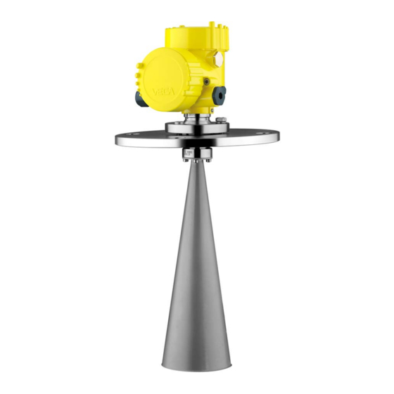
Vega VEGAPULS 68 Quick Setup Manual
Radar sensor for continuous level measurement of bulk solids
Hide thumbs
Also See for VEGAPULS 68:
- Operating instructions manual (105 pages) ,
- Quick setup manual (24 pages) ,
- Product information (20 pages)

Subscribe to Our Youtube Channel
Related Manuals for Vega VEGAPULS 68


Summary of Contents for Vega VEGAPULS 68
- Page 1 Quick setup guide Radar sensor for continuous level measurement of bulk solids VEGAPULS 68 4 … 20 mA/HART - four-wire Document ID: 51905...
-
Page 2: Table Of Contents
"www.vega.com". Operating instructions VEGAPULS 68 - 4 … 20 mA/HART - four- wire: Document-ID 29262 Editing status of the quick setup guide: 2018-02-16 VEGAPULS 68 • 4 … 20 mA/HART - four-wire... -
Page 3: For Your Safety
During work on and with the device the required personal protective equipment must always be worn. Appropriate use VEGAPULS 68 is a sensor for continuous level measurement. You can find detailed information about the area of application in chapter "Product description". Operational reliability is ensured only if the instrument is properly used according to the specifications in the operating instructions manual as well as possible supplementary instructions. -
Page 4: Safety Label On The Instrument
EN 302372 - Tank Level Probing Radar It is hence approved for use inside closed vessels in countries of the Use is also approved in EFTA countries, provided the respective standards have been implemented. VEGAPULS 68 • 4 … 20 mA/HART - four-wire... -
Page 5: Fcc And Ic Conformity (Only For Usa/Canada)
FCC ID: O6QPULS68 • IC: 3892A-PS68 Modifications not expressly approved by VEGA will lead to expiry of the operating licence according to FCC. VEGAPULS 68 is in conformity with part 15 of the FCC regulations. Take note of the respective operating regulations: • This device may not cause interference, and •... -
Page 6: Product Description
"VEGA Tools" and "Instrument search". You can find the serial number on the inside of the instrument as well as on the type label on the outside. Alternatively, you can access the data via your smartphone: • Download the VEGA Tools app from the "Apple App Store" or the "Google Play Store" • Scan the Data Matrix code on the type label of the instrument or •... -
Page 7: Mounting
3 Mounting Mounting Mounting preparations - Horn antenna VEGAPULS 68 is also available in versions where the antenna has a bigger diameter than the process fitting (thread, flange). The antenna must therefore be disconnected from the process fitting before mount- ing. Proceed as follows: 1. Loosen the hexagon socket screws (3) on the antenna socket with an Allen wrench (size 3) 2. Remove the antenna (4) Note: The plastic cone may not be pulled out of the antenna socket. -
Page 8: Mounting Instructions
8. Remount the parabolic antenna (4) 9. Tighten compression nut (1) with SW 41, torque max. 50 Nm 10. Tighten counter nut (2) with SW 36, torque max. 40 Nm. Note: Take note for VEGAPULS 68 with rinsing air connection that the holes in the antenna and in the process fitting correspond. This ensures a sufficient air flow (the air is led through the holes to the feed system. A rinsing of the parabolic antenna in total is not intended). Fig. 2: Dismounting, parabolic antenna... - Page 9 Fig. 3: Distance of the antenna to the vessel wall/vessel ceiling 2. Note min. socket diameter depending on the socket length 3. Note the instructions for sealing For further information see chapter "Mounting". VEGAPULS 68 • 4 … 20 mA/HART - four-wire...
-
Page 10: Connecting To Power Supply
10. Connect the screen to the internal ground terminal, connect the external ground terminal to potential equalisation 11. Tighten the compression nut of the cable entry gland. The seal ring must completely encircle the cable 12. Screw the housing lid back on The electrical connection is finished. VEGAPULS 68 • 4 … 20 mA/HART - four-wire... -
Page 11: Wiring Plan, Double Chamber Housing
4 Connecting to power supply Wiring plan, double chamber housing The following illustrations apply to the non-Ex as well as to the Ex-ia version. Wiring plan 4...20mA L1 N 4 ... 20 mA Fig. 5: Wiring plan - double chamber housing Voltage supply Signal output VEGAPULS 68 • 4 … 20 mA/HART - four-wire... -
Page 12: Set Up With The Display And Adjustment Module Plicscom
The display and adjustment module is powered by the sensor, an ad- ditional connection is not necessary. Fig. 6: Insert display and adjustment module Note: If you intend to retrofit the instrument with a display and adjustment module for continuous measured value indication, a higher lid with an inspection glass is required. VEGAPULS 68 • 4 … 20 mA/HART - four-wire... -
Page 13: Setup Steps
To indicate the actual level, the measured distance must be assigned to a certain height percentage. To perform the adjustment, enter the distance with full and empty ves- sel, see the following example: VEGAPULS 68 • 4 … 20 mA/HART - four-wire... - Page 14 2. Select the menu item "Service" with [->] and confirm with [OK]. Now the menu item "False signal suppression" is displayed. 3. Confirm "False signal suppression - Change now" with [OK] and select in the below menu "Create new". Enter the actual distance VEGAPULS 68 • 4 … 20 mA/HART - four-wire...
-
Page 15: Menu Schematic
Sensor Display Basic adjustment ▶ Display Diagnostics Service Info Displayed value Display unit Scaling Backlight ▼ ▼ Scaled 0 % = 0.0 l Volume Switched off ▼ 100 % = 100.0 l VEGAPULS 68 • 4 … 20 mA/HART - four-wire... - Page 16 Copy sensor data? Enable? Address 0 Info Basic adjustment Display Diagnostics Service ▶ Info Instrument type Date of manufacture Last change using PC Sensor characteristics Software version Display now? Serial number VEGAPULS 68 • 4 … 20 mA/HART - four-wire...
-
Page 17: Supplement
(optional) – 1 x closing cap ½ NPT, 1 x blind plug ½ NPT, plug M12 x 1 for VEGADIS 61 (optional) – 1 x plug (depending on the version), 1 x blind plug M20 x 1.5; plug M12 x 1 for VEGADIS 61 (optional) Spring-loaded terminals for wire cross- < 2.5 mm² (AWG 14) section Voltage supply Operating voltage Ʋ Non-Ex and Ex-d instrument 20 … 72 V DC, 20 … 253 V AC, 50/60 Hz Max. power consumption 4 VA; 2.1 W VEGAPULS 68 • 4 … 20 mA/HART - four-wire... - Page 18 Notes VEGAPULS 68 • 4 … 20 mA/HART - four-wire...
- Page 19 Notes VEGAPULS 68 • 4 … 20 mA/HART - four-wire...
- Page 20 Subject to change without prior notice © VEGA Grieshaber KG, Schiltach/Germany 2018 VEGA Grieshaber KG Phone +49 7836 50-0 Am Hohenstein 113...
Need help?
Do you have a question about the VEGAPULS 68 and is the answer not in the manual?
Questions and answers