Advertisement
Table of Contents
COMPONENTS:
TABLE
REF. #
QTY.
DESCRIPTION
1
1
R.H. END ASSEMBLY
2
1
L.H. END ASSEMBLY
3
1
FRONT RAIL
4
1
REAR RAIL
5
1
FOOT RAIL
6
1
DUST COVER
7
1
'H' FRAME
8
2
SUPPORT RAIL
OPTIONAL COMPONENTS:
The following components are in addition
to the TABLE components.
9
1
CENTER SUPPORT
10
2
DRAWER SLIDE
11
1
TOOL TRAY
12
1
TOOL DRAWER
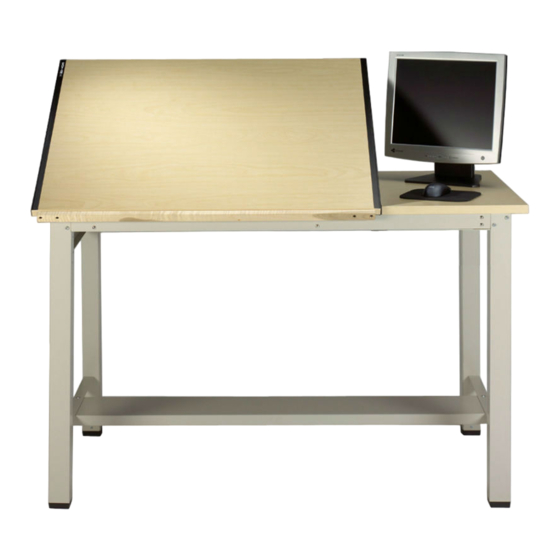
SPLIT TOP RANGER TABLE
When ordering components, specific color information may be required.
Contact a Mayline Customer Service Representative.
** Denotes Color Code
PART No.
A7560**
A7559**
B7650**
B7189**
B2026**
L4540
A4011**
B6543**
** Denotes Color Code
B7469**
B6361
F187
A7553**
ASSEMBLY INSTRUCTIONS
NOTE: Please count and inspect all pieces before
disposing of any carton or packing materials.
HARDWARE BAG
Part No. A7683 Ranger
Part No. A7684 Ranger with OPTIONAL Tool Drawer
TABLE *for individual item, order that part number
REF. #
QTY.
E1
2
E2
2
E3
8
E4
8
E5
12
E6
12
E7
10
E8
18
E9
2
E10
2
E11
4
E12
10
OPTIONAL COMPONENTS HARDWARE:
The following hardware is in addition to the
Table Hardware .
TOOL DRAWER ACCESSORY :
E13
6
E14
4
E15
1
E16
6
E17
6
E18
6
(1)
CATALOG No:
7772
7773
7772A 7773A
1-800-822-8037
DESCRIPTION
LOWER HINGE
UPPER HINGE
10-24 x 3/8 SCREW
10-24 KEPS NUT
1/4-28 x 3/8 SCREW
1/4-28 KEPS NUT
8 x 5/8 SCREW
10 x 3/4 SCREW
BUMPER
LIFT ASSEMBLY
10-32 x 1/2 FLAT HEAD SCREW
10-32 x 1/2 PAN HEAD SCREW
10-24 x 3/8 SCREW
10-24 KEPS NUT
HANDLE
8-32 x 3/8 THRD. CUTTING SCREW
8-32 x 5/16 MACHINE SCREW
8-32 ACORN NUT
PART No.
B195*
B194*
X147*
T2*
X156*
T25*
X140A*
X11*
D10*
V120A*
X191*
X204*
X147*
T2*
Q35*
X247*
X384*
T129*
Advertisement
Table of Contents

Subscribe to Our Youtube Channel
Related Manuals for Mayline Ranger 7772


Summary of Contents for Mayline Ranger 7772
- Page 1 7772A 7773A NOTE: Please count and inspect all pieces before disposing of any carton or packing materials. When ordering components, specific color information may be required. Contact a Mayline Customer Service Representative. 1-800-822-8037 COMPONENTS: HARDWARE BAG Part No. A7683 Ranger...
- Page 2 Assemblies with four Screws (E5) and Nuts (E6). TIGHTEN all rail attaching screws now. 3. Turn assembled table to an upright position. MAYLINE recommends that two people perform this task. 4. Attach the Support Channels (8) to the 'H' Frame (7) using #10-32 x 1/2 Screws (E12).
- Page 3 7. Attach the Upper Hinges (E2) to the underside of the Tilt Top with #10 x 3/4 Particle Board Screws (E8). Position with the hinge tab toward the front edge of the top. 8. Attach Lift Assembly (E10) to the 'H' Frame cross rail with #10-32 x 1/2 Flat Head Screws (E11).
- Page 4 1. Separate the Drawer Slides (10) into two pieces. Extend the Slide to the full extension. Remove the smaller portion (10B) by pressing the plastic release and pulling. 2. Attach the large Slide portion (10A) to the Center Support (9) using two Screws (E16).
Need help?
Do you have a question about the Ranger 7772 and is the answer not in the manual?
Questions and answers