Advertisement
Quick Links
MODELS:
7774..........LPL SURFACE
7774L........HPL SURFACE
7774A........LPL SURFACE / TOOL DRAWER
7774LA......HPL SURFACE / TOOL DRAWER
7774B........LPL SURFACE / TOOL & REF.DRAWERS
7774LB......HPL SURFACE / TOOL & REF. DRAWERS
Table of Contents.......................................................page 1
Tools and Safety........................................................page 2
Exploded View with B.O.M (Table).............................page 3
Exploded View with B.O.M (Optional Drawers)..........page 4
Hardware B.O.M........................................................ page 5 & 6
Assembly Instructions (Table)....................................page 7-9
Assembly Instructions (Optional Drawers).................page 10-13
Assembly Instructions (Tilt Top & Reference Top).....page 14
Installation (Tilt Top, Dust Cover, Reference Top).....page 15
I922
9-16
REV. 2
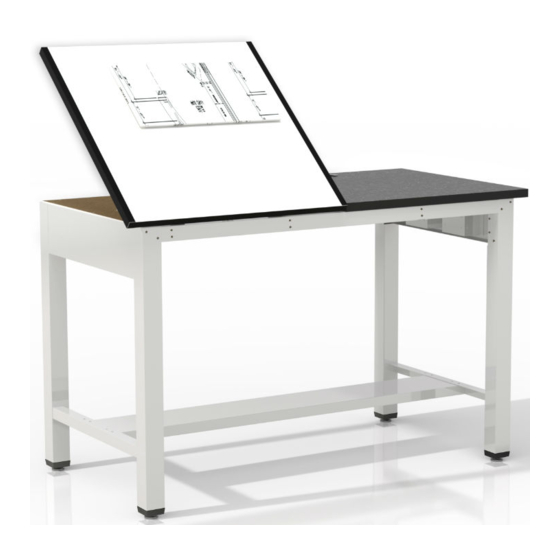
50/50 Split Top Ranger Table
7774A & 7774LA
1
7774 & 7774L
7774B & 7774LB
R
Advertisement

Subscribe to Our Youtube Channel
Related Manuals for Mayline 50/50 Split Top Ranger Table 7774


Summary of Contents for Mayline 50/50 Split Top Ranger Table 7774
- Page 1 50/50 Split Top Ranger Table MODELS: 7774..LPL SURFACE 7774L..HPL SURFACE 7774A..LPL SURFACE / TOOL DRAWER 7774LA..HPL SURFACE / TOOL DRAWER 7774B..LPL SURFACE / TOOL & REF.DRAWERS 7774LB..HPL SURFACE / TOOL & REF. DRAWERS 7774 & 7774L 7774A & 7774LA 7774B & 7774LB Table of Contents............page 1 Tools and Safety............page 2 Exploded View with B.O.M (Table)......page 3...
- Page 2 #2 PHILLIPS SCREWDRIVER problems that may occur from improper assembly or installation. 7/16" WRENCH Mayline and/or its distributor are not responsible for failure resulting from 3/8" WRENCH improper assembly or installation of this product. Moreover, all warranties are void for failure to follow these assembly instructions.
- Page 3 50/50 Split Top Ranger Table ITEM QTY DESCRIPTION PART No. END ASSEMBLY, L.H. 29.62 X 34.97 A7917 END ASSEMBLY, R.H. 29.62 X 34.97 A7918 BACK RAIL 50/50 SPLIT TOP 55.19 B9600 FOOT RAIL B2026 RAIL, SPLIT 50/50 FRONT 55.19 B9599 RANGER, SPLIT 50/50 SIDE REF.
- Page 4 50/50 Split Top Ranger Table "OPTIONAL" Drawer Components ITEM QTY DESCRIPTION PART No. PROGRESSIVE SLIDE B6361 DRAWER, REFERENCE WELD ASM A7655 SUPPORT, CENTER B7469 DRAWER, TOOL WELD ASM A7553 PLASTIC TRAY, 4 POST F187...
- Page 5 50/50 Split Top Ranger Table Hardware Bag Contents - BASE (A9249): Qty. Qty. Name Part Name Part X156 B194 PRHMS Upper Hinge #1/4-28 x 3/8" X191 B195 PFHTC Lower Hinge #10-32 x 1/2" X453 X204 Glide PPHTC #10-32 x 1/2" V120A KEPS Nut Lift Assembly...
- Page 6 50/50 Split Top Ranger Table Hardware Bag Contents - Pencil Stop OPTIONAL Drawers: Replacement Parts Qty. Qty. Name Part Name Part X384 PPHMS B9718 #8-32 x 5/16" Pencil Stop T129 Acorn Nut Pan Head Screw #8-32 #10 x 3/4 " X247 992102 PPHTC...
- Page 7 50/50 Split Top Ranger Table X204 PPHTC #10-32 x 1/2" NOTE: These diagonal holes indicate front of the 'H' frame. 'FLIP' for assembly 1" 7/8" Diagonal holes 'DOWN' Diagonal holes 1. Position the 'H' Frame (10) with the diagonal holes 'DOWN' toward the FRONT AND DOWN.
- Page 8 For tables without Optional Drawers - continue assembly on page 13 with Tilt 7. Install Glides (C) into the End Assemblies. Top and Reference Top assembly 8. Turn assembled table to an upright position. MAYLINE recommends that two people perform this task.
- Page 9 50/50 Split Top Ranger Table B195 LOWER HINGE X204 PPHTC #10-32 x 1/2" 9. Attach Lower Hinges (B) to 'H' frame with #10-32 x 1/2 Thread Cutting Screw (S). Position with hinge slot toward front of table. For tables without Optional Drawers - continue assembly on page 14 with Tilt Top and Reference Top assembly...
- Page 10 50/50 Split Top Ranger Table "OPTIONAL" Drawer Assembly X247 PPHTC #8-32 x 3/8" "PRESS" PULL Begin Begin "HERE" "HERE" TOOL REFERENCE DRAWER SLIDE DRAWER SLIDE 10. Separate the Drawer Slides (12) into two pieces (12A & 12B). Extend the Slide to the full extension. Remove the smaller portion (12B) by pressing the plastic release and pulling.
- Page 11 50/50 Split Top Ranger Table "OPTIONAL" Drawer Assembly X247 PPHTC #8-32 x 3/8" Begin "HERE" Begin "HERE" L.H. Side - Reference Drawer R.H. Side - Tool Drawer 12. Attach one large Slide portion (12A) to the brackets on the End Assemblies (1 & 2) using two Screws (S). Using the LOWER set of holes for Tool Drawer installation (R.H.
- Page 12 50/50 Split Top Ranger Table "OPTIONAL" Drawer Assembly X147 PTHMS #10-24 x 3/8" Begin "HERE" X384 PPHMS #8-32 x 5/16" T129 ACORN NUT #8-32 HANDLE Begin "HERE" LOCK 13. Attach the smaller Slide portion (12B) to each side of the Tool Drawer (15) using three Screws (Q) and three Acorn Nuts (R).
- Page 13 50/50 Split Top Ranger Table "OPTIONAL" Drawer Assembly X147 PTHMS #10-24 x 3/8" KEPS NUT #10-24 15. Install the assembled Center Support (14) into the Base. Attach the Support with two Screws (F) and two Nuts (M) per front and rear rail.
- Page 14 50/50 Split Top Ranger Table B194 16. Attach the Upper Hinges (A) Underside UPPER HINGE to the underside of the Tilt Top (Tilt Top) (7) with #10 x 3/4 Particle Board Screws (N). Position with the hinge tab toward the front edge PAN HEAD SCREW of the top.
- Page 15 50/50 Split Top Ranger Table V120A LIFT ASSEMBLY X140A PTHSMS #8 x 5/8" X191 PFHTC #10-32 x 1/2" PAN HEAD SCREW #10 x 3/4 " RUBBER BUMPER 19. Attach Lift Assembly (D) to the 'H' Frame cross rail with #10-32 x 1/2 Flat Head Screws (J). 20.
Need help?
Do you have a question about the 50/50 Split Top Ranger Table 7774 and is the answer not in the manual?
Questions and answers