Advertisement
Quick Links
o
re l ffice
Aberdeen Series
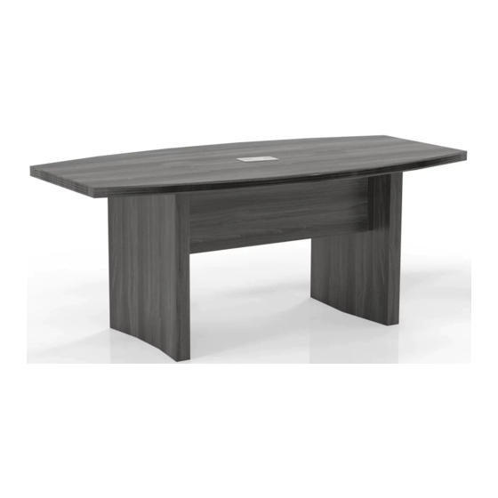
Conference Table 72" x 36"
Model No. ACTB6
ASSEMBLY INSTRUCTIONS
CALL 1-800-822-8037 FOR ASSISTANCE
P/N
ACTB6 REV 06 07/22/14
TM
www.mayline.com
PARTS LIST
Spare
Name
Part
Qty.
Qty
HB
A
8
2
REALS004
Wood Dowel
HB
B
18
2
HB
C
18
2
HB
D
18
2
Items with HB are in hardware box.
**Denotes Color Code
Spare
Name
Part
Qty.
HB
E
1
REALS099
Grommet
HB
F
4
REALS067
Leveler
1
Qty
Advertisement

Related Manuals for Mayline ACTB6


Summary of Contents for Mayline ACTB6
- Page 1 Name Part Qty. Qty. Conference Table 72" x 36" Model No. ACTB6 REALS004 REALS099 Wood Dowel Grommet REALS067 Leveler ASSEMBLY INSTRUCTIONS Items with HB are in hardware box. CALL 1-800-822-8037 FOR ASSISTANCE **Denotes Color Code ACTB6 REV 06 07/22/14 www.mayline.com...
-
Page 2: Parts List
These instructions are provided to avoid problems that may occur from improper assembly or installation. Mayline and/or its distributor are not responsible for failure resulting from improper assembly or installation of this product. Moreover, all warranties are void for failure NOTE: The arrow on the face of the Cam (C) to follow these assembly instructions. - Page 3 Insert Wood Dowels (A) into the top of the Table Legs (L) and Modesty Panels (K). Insert Cams into the Modesty Panels (K). Install Cam Posts (B) into threaded inserts in the underside of the Top (J). Secure Top (J) to Modesty Panels (K) by turning Cams (C). Apply Cam Stickers (D) to exposed Cams (C).
- Page 4 Name Part Qty. Qty. Conference Table 96" x 48" Model No. ACTB8 REALS099 REALS004 Grommet Wood Dowel REAL067 Leveler ASSEMBLY INSTRUCTIONS Items with HB are in hardware box. CALL 1-800-822-8037 FOR ASSISTANCE **Denotes Color Code ACTB8 REV 07 08/09/10 www.mayline.com...
- Page 5 These instructions are provided to avoid problems that may occur from improper assembly or installation. Mayline and/or its distributor are not responsible for failure resulting from improper assembly or installation of this product. Moreover, all warranties are void for failure to follow these assembly instructions.
- Page 6 Insert Wood Dowels (A) into the top of the Table Legs (J) and Modesty Panels (K). Insert Cams into the Modesty Panels (K). Install Cam Posts (B) into threaded inserts in the underside of the Top (L). Secure Top (L) to Modesty Panels (K) by turning Cams (C). Apply Cam Stickers (D) to exposed Cams (C).
- Page 7 Cam Post Plate 24 2 REALS001 REALS118 Cam Fastener Center Plate 24 2 REALS102** REALS043 Cam Sticker M6 x 15mm ACBT10HB ASSEMBLY INSTRUCTIONS REALS067 Items with HB are in hardware box Leveler CALL 1-800-822-8037 FOR ASSISTANCE ACTB10 REV 08 07/22/14 www.mayline.com...
- Page 8 Review ALL instructions before beginning assembly. These instructions are provided to avoid problems that may occur from improper assembly or installation. Mayline and/or its distributor are not responsible for failure resulting from improper assembly or installation of this product. Moreover, all warranties are void...
- Page 9 Insert Wood Dowels (A) into top edge of each Modesty Panel (P). Insert Install Cam Posts (B) into threaded inserts into the underside of each Wood Dowels (A) and Cams (C) into the end of each Modesty Panel Top (L). Attach Plates (H &...
- Page 10 Place each Top (L) onto the base. Fasten tops (L) together using Plates (G, H) and Screws (J). Secure Tops (L) to base by turning Cams (C). Insert Grommet (F) into Tops (L). Apply Cam Stickers (D) to all exposed Cams (C).
- Page 11 Cam Post Plate 24 2 REALS001 REALS118 Cam Fastener Center Plate 24 2 REALS102** REALS043 Cam Sticker M6 x 15mm ACBT10HB ASSEMBLY INSTRUCTIONS REALS067 Items with HB are in Leveler hardware box CALL 1-800-822-8037 FOR ASSISTANCE ACTB12 REV 08 07/22/14 www.mayline.com...
- Page 12 Review ALL instructions before beginning assembly. These instructions are provided to avoid problems that may occur from improper assembly or installation. Mayline and/or its distributor are not responsible for failure resulting from improper assembly or installation of this product. Moreover, all warranties are void for failure to follow these assembly instructions.
- Page 13 Insert Wood Dowels (A) into top edge of each Modesty Panel (P). Insert Install Cam Posts (B) into threaded inserts into the underside of each Wood Dowels (A) and Cams (C) into the end of each Modesty Panel Top (L). Attach Plates (H &...
- Page 14 Place each Top (L) onto the base. Fasten tops (L) together using Plates (G, H) and Screws (J). Secure Tops (L) to base by turning Cams (C). Insert Grommet (F) into Tops (L). Apply Cam Stickers (D) to all exposed Cams (C).
- Page 15 Cam Post Plate 38 2 REALS001 REALS118 Cam Fastener Center Plate 48 2 REALS102** REALS043 Cam Sticker M6 x 15mm ACBT18HB ASSEMBLY INSTRUCTIONS REALS067 Items with HB are in Leveler hardware box CALL 1-800-822-8037 FOR ASSISTANCE ACTB18 REV 04 07/22/14 www.mayline.com...
- Page 16 Review ALL instructions before beginning assembly. These instructions are provided to avoid problems that may occur from improper assembly or installation. Mayline and/or its distributor are not responsible for failure resulting from improper assembly NOTE: The arrow on the face of the Cam (C) or installation of this product.
- Page 17 Insert Wood Dowels (A) and Cams(C) into top edge of each Modesty Install Cam Posts (B) into threaded inserts into the underside of each Panel (S). Insert Wood Dowels (A) and Cams (C) into the end of each Top (N). Attach Plates (H &...
- Page 18 Place each Top (N) onto the base. Secure Top (N) to base by turning Install Cam Posts (B) into threaded inserts into the underside of each Cams (C). Insert Grommet (F) into Top (N). Apply Cam Stickers (D) to Top (L). all exposed Cams (C).
- Page 19 Place each Top (L) onto the base. Fasten tops (L) together using Plates (G, H) and Screws (J). Secure Tops (L) to base by turning Cams (C). Insert Grommet (F) into Tops (L). Apply Cam Stickers (D) to all exposed Cams (C).
Need help?
Do you have a question about the ACTB6 and is the answer not in the manual?
Questions and answers