
Related Manuals for socomec DIRIS B-10L


Summary of Contents for socomec DIRIS B-10L
- Page 1 INSTALLATION AND OPERATING MANUAL DIRIS B-10L Power Monitoring Device with wireless LoRaWAN communication...
-
Page 2: Table Of Contents
5.3.1. Optional module mounted on DIRIS B-10L ........ - Page 3 9.1.1. Connection modes ............9.1.2. Configuring the DIRIS B-10L using Easy Config System ......
- Page 4 11.1. DIRIS B-10L characteristics ........
- Page 5 DIRIS B-10L - 551174A - SOCOMEC...
-
Page 6: Documentation
1. DOCUMENTATION All documentation relating to the DIRIS B-30 and its associated sensors is available on the SOCOMEC website at the following address: www.socomec.com/en/diris-b DIRIS B-10L - 551174A - SOCOMEC... -
Page 7: Hazards And Warnings
The assembly, use, servicing and maintenance of this equipment must only be carried out by trained, qualified professionals. SOCOMEC shall not be held responsible for failure to comply with the instructions in this manual. 2.1. Risk of electrocution, burns or explosion Caution: risk of electric shock Ref. -
Page 8: Risk Of Damaging The Device
• The device must be positioned within an installation which complies with the standards currently in force. • Any cables which need to be replaced may only be replaced with cables with the correct ratings. DIRIS B-10L - 551174A - SOCOMEC... -
Page 9: Preliminary Operations
• The device has not been damaged during transportation, • The device reference number conforms to your order, • The packaging includes the device fitted with removable terminal blocks and a Quick Start guide. DIRIS B-10L - 551174A - SOCOMEC... -
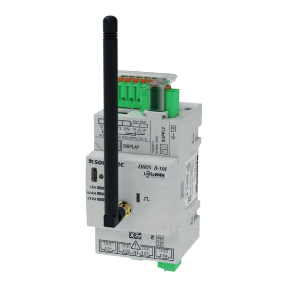
Page 10: Presentation
The DIRIS B-10L is designed for monitoring energy, power and various other parameters and can be used to jointly analyse single-phase and three-phase loads. Optional modules can be added to manage multi-utility energy meters (water, gas, etc.) and additional inputs/outputs (Digital, temperature, etc.) -
Page 11: Functions
4.1.2. Functions The DIRIS B-10L provides numerous functions and measurements: • General measurements - Current, frequency, voltage - Total Active Power (P) - Total Reactive Power (Q) - Total Apparent Power (S) - Total Power Factor (PFtot) - Class 0.5 for active energy and active power for the global measurement chain (including current sensors) according to IEC 61557-12. -
Page 12: Dimensions
4.1.3. Dimensions Dimensions in/mm 2.12 1.73 0.59 1.42 2.56 DIRIS B-10L - 551174A - SOCOMEC... -
Page 13: Optional Modules Presentation
4.2. Optional modules presentation The optional modules, which have a modular format, are fitted on the DIRIS B-10L ; they are used to extend its functionalities. 4.2.1. Range DIRIS O-iod DIRIS O-it Module with 2 digital inputs/outputs Module with 3 temperature inputs Ref. -
Page 14: Presentation Of The Remote Antenna
4.3. Presentation of the remote antenna When the DIRIS B-10L is installed inside an electrical panel, losses ranging from -15 to -10 dB must be taken into account and can have an impact on the strength of the signal. The DIRIS B-10L can be connected to a remote antenna, located outside the electrical panel: The remote antenna is connected to the DIRIS B-10L via a 3-meter SMA cable. -
Page 15: Presentation Of Associated Current Sensors
4.4. Presentation of associated current sensors Various types of current sensors can be connected to the DIRIS B-10L: solid core (TE), split core (TR/iTR) or flexible (TF). This makes the DIRIS B-10L suitable with all types of new or existing installations. A rapid RJ12 connection makes wiring easy and reliable and prevents wiring errors. -
Page 16: Te Solid-Core Current Sensors
75.6 A 192 A 300 A 756 A 1200 A 4829 0500 4829 0501 4829 0502 4829 0503 4829 0504 4829 0505 Reference TE-90 Pitch 90 mm Nominal current range 600 - 2000 A I Max 2400 A Reference 4829 0506 DIRIS B-10L - 551174A - SOCOMEC... -
Page 17: Dimensions
ø 9 13.5 x 13.5 21 x 21 31 x 31 41 x 41 0.69 0.69 0.77 0.85 17.5 17.5 19.5 21.5 TE-90 Dimensions in/mm 3.54 0.08 0.97 24.6 2.52 / 64 0.77 19.7 1.42 DIRIS B-10L - 551174A - SOCOMEC... -
Page 18: Tr Split-Core Current Sensors
The TR split-core current sensors are used to set up measurement points in a new or existing installation without interfering with its cabling. Thanks to the specific link, they are recognised by the DIRIS B-10L and a high level of overall accuracy for the measurement chain is guaranteed. -
Page 19: Tf Flexible Current Sensors
The secure lock technology prevents non voluntary openings of the Rogowski rope. Thanks to the specific link, they are recognised by the DIRIS B-10L and a high level of overall accuracy for the measurement chain is guaranteed. 4.4.3.1. Range Six models are available, covering a large current range up to 6000 A with openings of different shapes and sizes. -
Page 20: Adaptor For 5A Or 1A Current Transformers
A secondary CT and 2000 A for a 1 A secondary CT. 4.4.4.1. Range 5A adaptor 5 A I name. 6 A I Max. 4829 0599 Reference 4.4.4.2. Dimensions 5A adaptor Dimensions in/mm 28 x 20 x 45 LxHxD Aperture (W) ø 9 DIRIS B-10L - 551174A - SOCOMEC... -
Page 21: Mounting
5. MOUNTING The following paragraphs describe the installation of the DIRIS B-10L, the optional modules and the associated sensors. 5.1. Recommendations and safety Refer to the safety instructions (section “2. Hazards and warnings”, page 7) 5.2. DIRIS B-10L mounting 5.2.1. DIN rail mounting... -
Page 22: Sealing Accessory For Sensors
5.2.3. Sealing accessory for sensors Sealing case for terminal Reference 4829 0600 5.3. Optional modules mounting 5.3.1. Optional module mounted on DIRIS B-10L DIRIS B-10L Optional module 5.3.2. Mounting an optional module on an optional module Optional module Optional module DIRIS B-10L - 551174A - SOCOMEC... -
Page 23: Te Solid-Core Sensors Mounting
4829 0501 4829 0502 TE-25 25 mm 4829 0503 35 mm TE-35 4829 0504 TE-45 45 mm 4829 0505 TE-55 55 mm 4829 0506 TE-90 90 mm 5.4.2. DIN rail mounting TE-18 -> TE-55 DIRIS B-10L - 551174A - SOCOMEC... - Page 24 TE-90 Removing clamps Fix sensor TE-90 to the DIN rail to make it easier to install. This is a temporary installation. Use the clamps to install the TE-90 sensors on the DIN rail. DIRIS B-10L - 551174A - SOCOMEC...
-
Page 25: Plate Mounting
5.4.3. Plate mounting TE-18 diameter 0.17 / 4.2 M4 max 1 Nm 1.05 26.8 0.81 20.5 TE-25 - > TE-55 diameter 0.20 / 5.2 M5 max 1 Nm DIRIS B-10L - 551174A - SOCOMEC... - Page 26 TE-90 Removing clamps diameter 0.20 diameter 5.2 Use the clamps to install the TE-90 sensors on the board. DIRIS B-10L - 551174A - SOCOMEC...
-
Page 27: Mounting On A Cable With Clamping Collar
Use the clamps to install the TE-90 sensors on a cable with clamping collar. Do NOT clamp or pull out NON-INSULATED conductors carrying DANGEROUS VOLTAGE which could cause an electric shock, burn or arc flash. Ref. IEC 61010-2-032 DIRIS B-10L - 551174A - SOCOMEC... -
Page 28: Busbar Mounting
The jaws must be perpendicular to the holding notches. Do NOT clamp or pull out NON-INSULATED conductors carrying DANGEROUS VOLTAGE which could cause an electric shock, burn or arc flash. Ref. IEC 61010-2-032 DIRIS B-10L - 551174A - SOCOMEC... -
Page 29: Sensors Assembly
Mounting accessories for combining sensors: Linear assembly Staggered assembly Reference 4829 0598 These accessories must be ordered separately. 5.4.7. Sealing accessories for sensors Sealing case for terminal Reference 4829 0600 These accessories must be ordered separately. DIRIS B-10L - 551174A - SOCOMEC... -
Page 30: Tr/Itr Split-Core Sensors Mounting
Do NOT clamp or pull out NON-INSULATED conductors carrying DANGEROUS VOLTAGE which could cause an electric shock, burn or arc flash. Ref. IEC 61010-2-032. Before closing the TR /iTR sensor, check that the air gap is clean (no contamination or corrosion). DIRIS B-10L - 551174A - SOCOMEC... -
Page 31: Tf Flexible Sensors Mounting
Centred position for the best measurement Do NOT clamp or pull out NON-INSULATED conductors carrying DANGEROUS VOLTAGE which could cause an Centred position for the best electric shock, burn or arc flash. measurement Ref. IEC 61010-2-032 DIRIS B-10L - 551174A - SOCOMEC... -
Page 32: Installing The 5A Adaptor
5.7. Installing the 5A adaptor 5A secondary current transformer Do NOT clamp or pull out NON-INSULATED conductors carrying DANGEROUS VOLTAGE which could cause an electric shock, burn or arc flash. Ref. IEC 61010-2-032 DIRIS B-10L - 551174A - SOCOMEC... -
Page 33: Connection
2 digital inputs 4 positions - screw 0.25 Nm max. solid 0.14 mm -> 1.5 mm stranded 0.14 mm -> 1.5 mm 7 mm (*) Do not forget to connect earth to the DIRIS B-10L. DIRIS B-10L - 551174A - SOCOMEC... - Page 34 Power supply of optional modules 110-230VAC OPTIONAL MODULE 4 OPTIONAL MODULE 3 OPTIONAL MODULE 2 OPTIONAL MODULE 1 DIRIS B *0.5 A gG / BS 88 2A gG / 0.5 A class CC fuse DIRIS B-10L - 551174A - SOCOMEC...
-
Page 35: Connecting The Optional Modules
2x4 positions - screw connection, 0.25 Nm max. 0.14 mm2-> 1.5 mm2 solid 0.14 mm2 -> 1.5 mm2 stranded 7 mm PT100 or PT1000 Power supply of optional DIRIS O-iod DIRIS O-it modules DIRIS O-iod and O-ioa INPUT OUTPUT DIRIS B-10L - 551174A - SOCOMEC... -
Page 36: Connecting The Current Sensors
B-10L Recommendations: For connecting the current sensors, use SOCOMEC cables only: RJ12 straight, twisted pair, unshielded,600 V, -10°C / +70°C as per IEC 61010-1 version 3.0. It is recommended that all the current sensors are installed in the same direction. -
Page 37: Details Of The Rj12 Connections For Each Current Sensor
6.3.2. Details of the RJ12 connections for each current sensor TE-18 to TE-55 TE-90 SOCOMEC cable for current sensors DIRIS B-10L TR /iTR Do not bring into contact with dangerous voltages SOCOMEC cable for current sensors DIRIS B-10L DIRIS B-10L - 551174A - SOCOMEC... -
Page 38: Connection To The Electrical Network And To The Loads
1, 2, 3 or 4 sensors for balanced or unbalanced loads. Several loads can be measured simultaneously. The overall accuracy of the DIRIS B-10L + sensors measurement chain is guaranteed. To guarantee this accuracy, SOCOMEC cables must be used for the current sensors. - Page 39 V1 V2 V3 VN V1 V2 V3 VN B-10L B-10L B-10L B-10L B-10L B-10L Fuse: 0.5 A gG / BS 88 2A gG / 0.5 A class CC V1 V2 V3 VN V1 V2 V3 VN DIRIS B-10L - 551174A - SOCOMEC...
-
Page 40: Connection Of The Functional Earth
B-10L 6.3.4. Connection of the functional earth It is recommended that the functional earth be connected to guarantee optimum measuring accuracy and better emissivity/ immunity for the electromagnetic compatibility (class B in conducted emission). DIRIS B-10L - 551174A - SOCOMEC... -
Page 41: Product Leds
LoRa card not started or not LoRa card is connected and LoRa card is pairing (Orange) connected to LoRa network operational Energy is flowing (corresponds to No energy flowing the metrological pulse weight) (Red) DIRIS B-10L - 551174A - SOCOMEC... -
Page 42: Lorawan Communication
8. LoRaWAN COMMUNICATION 8.1. General information LoRaWAN is a wireless communication protocol allowing to collect measurement data from remote DIRIS B-10L power monitoring devices. The DIRIS B-10L can communicate via a private LoRaWAN network or via an operated network. 8.2. LoRa Key Recovery •... - Page 43 • 4 bits: status change counter - Native Input 2 counter • 4 bits: status change counter - Digital Input 1 (optional module 1) • 4 bits: status change counter - Digital Input 2 (optional module 1) TOTAL 25 (50 bytes) DIRIS B-10L - 551174A - SOCOMEC...
- Page 44 • 4 bits: status change counter - Native Input 2 counter • 4 bits: status change counter - Digital Input 1 (optional module 1) • 4 bits: status change counter - Digital Input 2 (optional module 1) TOTAL 25 (50 bytes) DIRIS B-10L - 551174A - SOCOMEC...
- Page 45 • 4 bits: status change counter - VirtualMonitor iTR 2 • 4 bits: status change counter - VirtualMonitor iTR 3 • 4 bits: status change counter - VirtualMonitor iTR 4 TOTAL 25 (50 bytes) DIRIS B-10L - 551174A - SOCOMEC...
- Page 46 • 4 bits: status change counter - VirtualMonitor iTR 2 • 4 bits: status change counter - VirtualMonitor iTR 3 • 4 bits: status change counter - VirtualMonitor iTR 4 TOTAL 25 (50 bytes) DIRIS B-10L - 551174A - SOCOMEC...
- Page 47 • 4 bits: status change counter - VirtualMonitor iTR 2 • 4 bits: status change counter - VirtualMonitor iTR 3 • 4 bits: status change counter - VirtualMonitor iTR 4 TOTAL 25 (50 bytes) DIRIS B-10L - 551174A - SOCOMEC...
- Page 48 • 4 bits: status change counter - Native Input 2 Status change counter • 4 bits: status change counter - Digital Input 1 (optional module 1) • 4 bits: status change counter - Digital Input 2 (optional module 1) TOTAL 25 (50 bytes) DIRIS B-10L - 551174A - SOCOMEC...
-
Page 49: Lorawan To Ethernet Modbus Tcp Gateway
DATALOG H DIRIS B-10L Ethernet LoRa Gateway Core network embedded DIRIS B-10L Modbus registers The LoRaWAN gateway re-creates a Modbus table containing the different measurements from the DIRIS B-10L General information Dec address Hex address Words count description Data Type... - Page 50 1 : Enabled Date of last 4289 0x10C1 DATETIME READ instance 4291 0x10C3 Wh 10 READ 4295 0x10C7 Wh 10 READ 4299 0x10CB varh 10 READ 4303 0x10CF varh 10 READ 4307 0x10D3 Reserved DIRIS B-10L - 551174A - SOCOMEC...
- Page 51 0x204A READ 1 : Lagging 2 : Leading 8267 0x204B Average Current phase 1 READ 8269 0x204D Average Current phase 2 READ 8271 0x204F Average Current phase 3 READ 8273 0x2051 Average Frequency READ DIRIS B-10L - 551174A - SOCOMEC...
- Page 52 0x20CA READ 1 : Lagging 2 : Leading 8395 0x20CB Average Current phase 1 READ 8397 0x20CD Average Current phase 2 READ 8399 0x20CF Average Current phase 3 READ 8401 0x20D1 Average Frequency READ DIRIS B-10L - 551174A - SOCOMEC...
- Page 53 Hex address Words count Description Unit Data type Function Profil Sensor status 12288 0x3000 0 : Disabled READ 1/2/3 1 : Enabled 12289 0x3001 Date of last instance DATETIME READ 1/2/3 12291 0x3003 Total 1/2/3 DIRIS B-10L - 551174A - SOCOMEC...
- Page 54 Flag - previous point 0 : Complete period - date configured 16406 0x4016 1 : Incomplete period - date not configured READ 2 : Complete period - date configured 3 : Incomplete period - date not configured DIRIS B-10L - 551174A - SOCOMEC...
- Page 55 Flag - previous point 0 : Complete period - date configured 16470 0x4056 1 : Incomplete period - date not configured READ 2 : Complete period - date configured 3 : Incomplete period - date not configured DIRIS B-10L - 551174A - SOCOMEC...
- Page 56 Flag - previous point 0 : Complete period - date configured 16534 0x4096 1 : Incomplete period - date not configured READ 2 : Complete period - date configured 3 : Incomplete period - date not configured DIRIS B-10L - 551174A - SOCOMEC...
- Page 57 Flag - previous point 0 : Complete period - date configured 16598 0x40D6 1 : Incomplete period - date not configured READ 2 : Complete period - date configured 3 : Incomplete period - date not configured DIRIS B-10L - 551174A - SOCOMEC...
- Page 58 Digital Input 1 – Optional module 4 20492 0x500C READ 1/2/3/4/5/6/7 0 : N/A 1 : Active Digital Input 2 – Optional module 4 20493 0x500D READ 1/2/3/4/5/6/7 0 : N/A 1 : Active DIRIS B-10L - 551174A - SOCOMEC...
- Page 59 Protection Alarm #2 28691 0x7013 0 : N/A READ 1 : Active Protection Alarm #3 28692 0x7014 0 : N/A READ 1 : Active Protection Alarm #4 28693 0x7015 0 : N/A READ 1 : Active DIRIS B-10L - 551174A - SOCOMEC...
-
Page 60: Eu Declaration Of Conformity
1 : Active System Alarm #4 (Bad CT primary) 28699 0x701B 0 : N/A READ 1 : Active 8.5. EU Declaration of Conformity The EU Declaration of Conformity for the DIRIS B-10L is available here: www.socomec.com/en/diris-b DIRIS B-10L - 551174A - SOCOMEC... -
Page 61: Configuration
- Click on “New Configuration”, then enter a name and icon. - Click on the newly created configuration. - Click on “USB mode” on the right top corner to connect to the DIRIS B-10L via a USB cable. - Go to the “PARAMETERS” part to configure the different menus: •... - Page 62 ƒ Sources: select the source for the position and trip information. When iTR sensors are used, the VirtualMonitor technology is used. ƒ Thresholds: used to differentiate between no-load, on-load and overload manual openings and trips. DIRIS B-10L - 551174A - SOCOMEC...
-
Page 63: Configuration From The Diris D-30 Remote Display
- Date/time: to manually synchronise the date/time of the DIRIS B-10L with the computer’s date and time. • Commands - Reset: to reboot the DIRIS B-10L, reset alarm logs, Min/Max values, partial meters or restore the device to its factory default settings. -
Page 64: Alarms
A time delay at the start and end of the alarm can be set for each alarm. A digital output can be associated to each alarm to report the alarm on an output. The alarm can be acknowledged automatically or using a digital input. DIRIS B-10L - 551174A - SOCOMEC... -
Page 65: Protection Alarms
10.3. Protection alarms The DIRIS B-10L includes 6 protection alarms alerting the user of an event on a protective device. Make sure you have configured the protective device type used in the “Protection” menu in order to use the Protection alarms Protection alarms can be configured in case of: - An opening of the protective device. -
Page 66: Technical Characteristics
IP20 / IK06 Index of protection of front side IP40 on the nose in modular assembly / IK08 Sealing for the voltage and current connections Sealable enclosure option for DIRIS B-10L and sensors: ref: 4829 0597 Weight DIRIS B-10L: 195 g 11.1.2. -
Page 67: Measuring Characteristics
Specific Socomec cable with RJ12 connectors 11.1.5. Communication characteristics Link Wireless Protocol LoRaWAN Bandwidth 863 - 870 MHz Europe Port Class Class C Power Level 14 dBm Version 1.0.3 Spreading Factor SF7 to SF12 Activation Method OTAA DIRIS B-10L - 551174A - SOCOMEC... -
Page 68: Environmental Characteristics
Compliance with Low Voltage Directive 2014/35/EU of 26 February 2014 (IEC EN61010-1 & IEC EN61010-2- 030) Insulation Installation category III (300 VAC Ph/N), degree of pollution 2 11.1.9. Service life MTTF (mean time to failure) > 100 years DIRIS B-10L - 551174A - SOCOMEC... -
Page 69: Diris O Optional Modules Characteristics
-20 °C to 150 °C Type PT100 or PT1000 Function of inputs 1, 2 and 3 Temperature measurement 3 removable screw terminal blocks, 3 x 4 positions, stranded or solid Connection 0.14 - 1.5 mm² cable (length max. 3 m) DIRIS B-10L - 551174A - SOCOMEC... -
Page 70: Diris D-30 Display Characteristics
24 VDC +10 % / -20 % Power consumption 2 VA 11.3.4. Environmental characteristics Storage temperature range -20 ... +70°C Operating temperature range -10 ... +55°C Humidity 95% at 40°C Installation category CAT III Degree of pollution DIRIS B-10L - 551174A - SOCOMEC... -
Page 71: Te, Tr /Itr And Tf Sensors - Characteristics
95% RH without condensation Altitude < 2,000 m PEP ecopassport - ISO 14025 TE sensors: SOCO-2014-03-v1-fr, SOCO-2014-03-v1-en UL 61010 SOCOMEC RJ12 cable, straight, twisted pair, unshielded, Connection 300 V cat.III. -40/+85°C. (1) > 1000A with 5A TC adapter. TE - solid-core current sensor TE-90 Model... - Page 72 -10 - +70°C Operating temperature -25 - +85°C Storage temperature 95% RH without condensation Relative humidity < 2,000 m Pollution degree TR sensors: SOCO-2014-04-v1-fr, SOCO-2014-04-v1-en SOCOMEC RJ12 cable, straight, twisted pair, unshielded, 300 V cat.III. Connection -40/+85°C. TF - Flexible current sensor Model TF-40 TF-80 TF-120 TF-200...
-
Page 73: Performance Classes
1 in combination with TR sensors 12.1. Specification of the characteristics Overall operating performance class of Measurement Symbol Function DIRIS B-10L + dedicated sensors * (TE, TR range /iTR, TF) compliant with IEC 61557-12 Total active power 0.2 DIRIS B-10L alone 10% - 120% In 0.5 with TE, iTR or TF sensors... -
Page 74: Evaluation Of The Power Supply Quality
Voltage outage (Lp-Lg or Lp-N) Unba Voltage amplitude unbalance (Lp-N) Voltage phase and amplitude unbalance (Lp-Lg or Lp-N) Voltage harmonics Current harmonics 1 with TE, TR /iTR or TF sensors Centralised remote control signals DIRIS B-10L - 551174A - SOCOMEC... - Page 75 DIRIS B-10L - 551174A - SOCOMEC...
- Page 76 CORPORATE HQ CONTACT: SOCOMEC SAS 1-4 RUE DE WESTHOUSE 67235 BENFELD, FRANCE www.socomec.com 551174A...
Need help?
Do you have a question about the DIRIS B-10L and is the answer not in the manual?
Questions and answers