
Related Manuals for ClearSpan 105115


Summary of Contents for ClearSpan 105115
- Page 1 High-Crown Arena ClearSpan™ High-Crown Arena 60' Diameter ©2006 ClearSpan™ Sku: #105115 All Rights Reserved. Reproduction is prohibited without permission. Revision date: August 2006jg...
- Page 2 1. Verify that all parts are included in the shipment. consult local contractors for assistance before you dig Notify Customer Service for questions or concerns. and prepare to set the ground posts. Visit www.ClearSpan.com for additional products and customer assistance. 1 of 36...
- Page 3 The words and phrases that follow are common to many ClearSpan™ shelters and identify the different parts of a • Tek Screw: A self-tapping fastener used to secure shelter.
-
Page 4: Required Tools
QUICK-START GUIDE For a quick overview of this arena, consult all diagrams and photos and the Quick-Start Guide near the end of this instruction manual. Visit www.ClearSpan.com for additional products and customer assistance. 3 of 36... - Page 5 Base plate is not used for this arena. The bolt, lock washer, and nut are used to attach the pipe fitting to the ground posts. 10015108 Single-Socket Tee for Sidewall Visit www.ClearSpan.com for additional products and customer assistance. 4 of 36...
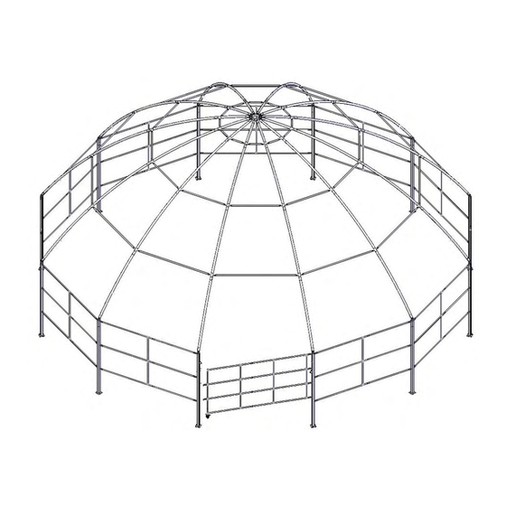
- Page 6 Crown (105099) Frame Diagram: 60' High- Crown Arena Support Purlins (3) Rings Diagonal Cable Ground Post Sidewall Frame 4' of post is below finished grade Gate Visit www.ClearSpan.com for additional products and customer assistance. 5 of 36...
- Page 7 The ground posts on either side of the gate opening are DA4X4PAR DA4X4PAD different from the remaining ground posts and must be positioned where the gate will be located. Visit www.ClearSpan.com for additional products and customer assistance. 6 of 36...
- Page 8 (4'). Sidewall framing and the gate will be at or near ground level when installed properly, which is a view that is not shown in the diagrams. Visit www.ClearSpan.com for additional products and customer assistance. 7 of 36...
- Page 9 104302 assembly. (See Pictorial Parts Guide ID page if needed.) 12. Repeat the above procedure to install the remaining sections of frame between the ground posts. Visit www.ClearSpan.com for additional products and customer assistance. 8 of 36...
- Page 10 Start at the first joint between the first two rafter pipes and insert a coupler. Use a punch or screwdriver to align the holes if needed. 105092 End Pipe Connector Visit www.ClearSpan.com for additional products and customer assistance. 9 of 36...
- Page 11 (See Rafter Diagram for placement.) 9. Repeat the steps to assemble all remaining rafters. 10. Once all rafters are assembled, continue with installing the rafters and assembling the frame. Visit www.ClearSpan.com for additional products and customer assistance. 10 of 36...
- Page 12 See the diagrams above. Gate Location Photo shows lifting a rafter into position. Arena shown Diagram shows the top view with three rafters installed. may be of a similar model. Visit www.ClearSpan.com for additional products and customer assistance. 11 of 36...
- Page 13 Tek Screws Diagram shows the ring bracing for the bottom ring of 7. Once the rafter frame is assembled, install the the arena. purlins for the ring bracing. Visit www.ClearSpan.com for additional products and customer assistance. 12 of 36...
- Page 14 At this time, the loose end of each 32' cable will hang from the crown to the center of the arena. Visit www.ClearSpan.com for additional products and customer assistance. 13 of 36...
- Page 15 Cable 9. Using two (2) additional cable clamps, secure the cable around the end pipe connector as you did at the crown. See Step 3 if needed. Visit www.ClearSpan.com for additional products and customer assistance. 14 of 36...
- Page 16 2. Take one 20' cable, determine where on that cable you want to position a turnbuckle, and cut the cable at that location. For cables attached at the purlin brackets, consult the photo that follows. Visit www.ClearSpan.com for additional products and customer assistance. 15 of 36...
- Page 17 6. Once all long cables are snug, move to the cross cables at one location and measure diagonally from connection point to connection point for each cable pair. See the diagram on the following page. Visit www.ClearSpan.com for additional products and customer assistance. 16 of 36...
- Page 18 3. Attach the end pipe connectors that are used to attach the assembled gate to the ground posts at one end and to secure the gate closed at the other. Visit www.ClearSpan.com for additional products and customer assistance. 17 of 36...
- Page 19 8. With the cable secured to the gate, tighten the turnbuckle to support the gate. 9. Continue by installing the main cover. Use of wheel depends on site. Cable will support gate without wheel. Visit www.ClearSpan.com for additional products and customer assistance. 18 of 36...
- Page 20 Tek Screws 1. Spread the main cover out on the ground near the assembled frame with the top/outside of the cover facing up. Black straps will be on the underside. Visit www.ClearSpan.com for additional products and customer assistance. 19 of 36...
- Page 21 7. As the cover is unrolled in the final two directions, temporarily secure the cover to the rafters using the straps at the top and at the mid locations. Straps are Visit www.ClearSpan.com for additional products and customer assistance. 20 of 36...
- Page 22 8. Continue pulling the cover into position and using the straps to temporarily secure it to the rafters. NOTE: Verify that the ratchet does not touch the cover and that the cable does not hamper its operation. Visit www.ClearSpan.com for additional products and customer assistance. 21 of 36...
- Page 23 NOTE: Do not tighten at this time. 7. Move down the rafters to the mid ratchets and insert the corresponding strap into the ratchets to temporarily secure the cover. Visit www.ClearSpan.com for additional products and customer assistance. 22 of 36...
- Page 24 ATTENTION: Additional help is needed when feeding 9881.) the conduit into each pocket. 4. Once all cover conduits are in place, insert a cover coupler (60DA166C) to connect the conduit sections. See the following diagram. Visit www.ClearSpan.com for additional products and customer assistance. 23 of 36...
- Page 25 5. Repeat the procedure to install the remaining side ground posts. panels. 2. Insert the end of the tie-down through the grommet 6. Read the High Crown Arena Care and of the side panel. Maintenance information. Visit www.ClearSpan.com for additional products and customer assistance. 24 of 36...
- Page 26 • If the shelter is dismantled and moved, inspect all parts and connections before reassembly. • For replacement or missing parts, call 1-800-245-9881 for assistance. NOTE: With the exception of Truss Arch buildings, ClearSpan™ shelters and greenhouses do not have any tested loading criteria.
- Page 27 ATTENTION: Vertical pipes (#190P045) are 45" long. MOUNTING BOLTS: Use the 1/2" carriage bolts, lock washers, and nuts that remain after you disassemble the 104302 assembly. See the Pictorial Parts page if needed. Visit www.ClearSpan.com for additional products and customer assistance. 26 of 36...
- Page 28 (FAME09B), and 1/2" self-locking (4) Flat washers nuts (FALF23B). Install washer against nut. All remaining vertical pipes for the gate are 26 1/2" long. (4) Lock washers (4) Nuts Visit www.ClearSpan.com for additional products and customer assistance. 27 of 36...
- Page 29 36" NOTE: Attach band clamp no more than 36" from the top of sidewall ground post. Secure Rafter Splice clamp to the rafter with one Tek screw. Visit www.ClearSpan.com for additional products and customer assistance. 28 of 36...
- Page 30 60' HIGH CROWN ARENA GROUND POST PLACEMENT 60' HIGH CROWN ARENA GROUND POST PLACEMENT 60' HIGH CROWN ARENA GROUND POST PLACEMENT 60' HIGH CROWN ARENA GROUND POST PLACEMENT 42'-2 5/16" 42'-2 5/16" 42'-2 5/16" 42'-2 5/16" Inside Center to Inside Center to Inside Center to Inside Center to Inside Center...
- Page 31 Quick Start Guide High-Crown Arena 30 of 36...
- Page 32 CONNECTIONS Sidewall - Rafter Connection View 1 Cabling Pattern in every fourth bay. Rafter - Purlin Connection -3 bays total. View 2 Detail Outlined in instructions. 31 of 36...
-
Page 33: Connection Details
CONNECTION - DETAILS Rafter 3/8" x 1" hex bolt and nut with 1/2" x 5 1/2" hex bolt 3/8" flat washer lock washer and nut and 3/8" lock washer 1/2" x 4" hex bolt -Flat washer MUST Purlin lock washer and nut be installed on top of purlin -Lock washer MUST... - Page 34 DOOR PANEL DETAILS 190P074 190S099D Single-Socket Tee 190P0292 Two-Socket Cross 190P0795D 190P0265 190P0795D 190P0292 All other Door Vertical Pipes = 26.5" 190P074 Cable Assembly -Field drill through the horizontal pipes near the pipe couplers. (See instructions) 1/2" x 1 1/2" carriage bolt and nut with lock washer from 104302 foot Detail A...
- Page 35 SIDE PANEL DETAILS 105092 End Pipe Connector Single-Socket Tee QH1061 Ratchet 190S099D 190P0795D Two-Socket Cross 190P045 105098 Pipe Connector (From the 104302) Single-Socket Tee Visit www.ClearSpan.com for additional products and customer assistance. 34 of 36...
- Page 36 Cover Conduit Installation Guide 190S099 190P0795 60DA166C Coupler 190S099 Step 1. Assemble all sections of cover conduit using two (2) Tek Screws; one (1) on each side of the pipe. 190P0795 Insert all sections of Step 2. cover conduit into the cover pockets.
- Page 37 Customer Notes Visit www.ClearSpan.com for additional products and customer assistance. 36 of 36...
Need help?
Do you have a question about the 105115 and is the answer not in the manual?
Questions and answers