Advertisement
Quick Links
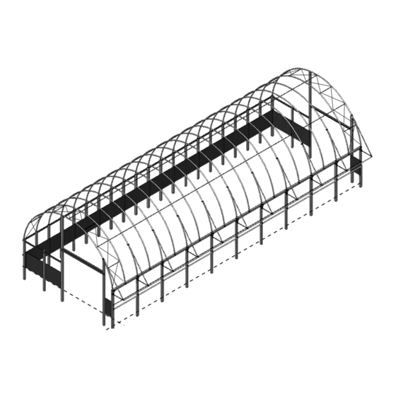
Photo may show a model of a different length. Cover, roll-up curtain, and end panels are not shown.
©2020 ClearSpan™
All Rights Reserved. Reproduction
is prohibited without permission.
Revision date: 05.20.20
ClearSpan
Beef Master
System
™
Ground Level
STK#
108440W
CLEARSPAN
™
DIMENSIONS
36' W x 26' 2" H x 100' L
POLY BUILDINGS
™
1
Advertisement

Related Manuals for ClearSpan Beef Master 108440W


Summary of Contents for ClearSpan Beef Master 108440W
- Page 1 ™ Beef Master System ™ Ground Level Photo may show a model of a different length. Cover, roll-up curtain, and end panels are not shown. ©2020 ClearSpan™ All Rights Reserved. Reproduction is prohibited without permission. STK# DIMENSIONS 108440W 36' W x 26' 2" H x 100' L...
-
Page 2: Safety Precautions
• Never erect the structure under power lines. • Identify whether underground cables and pipes are Thank you for purchasing this ClearSpan™ shelter. When present before preparing the site or anchoring the properly assembled and maintained, this product will structure. -
Page 3: Assembly Procedure
These words and phrases are common to most refers to the tapered end of the pipe or tube. Swaged ClearSpan™ shelters and identify the different parts of ends of a pipe can be inserted into couplers and the the shelter. (Some are used in this document. Others may straight ends of other pipes of the same diameter. - Page 4 CLEARSPAN POLY BUILDINGS ™ SPECIAL NOTE: Customer-Supplied Lumber The lumber needed for this building is not included with the ATTENTION: Changes made by the contractor/owner shipment and must be supplied by the customer. Treated specific to the desired results may require a materials lumber is recommended.
-
Page 5: Required Tools
CLEARSPAN POLY BUILDINGS ™ REQUIRED TOOLS AWNING PARTS LIST The following list identifies the main tools needed to The following graphics and photos will help you identify the assemble the shelter. Additional tools and supports may be different parts of the awning. Consult the Quick Start Guide needed. - Page 6 CLEARSPAN POLY BUILDINGS ™ The following graphics and photos will help you identify the different parts of the building. Consult the Quick Start Guide for additional details and diagrams. (Some parts are not shown.) FA4482B QH1061 100441 CP287X125E CP287X125M Tek Screw 1"...
- Page 7 CLEARSPAN POLY BUILDINGS ™ ClearSpan ™ Beef Master™ System ATTENTION: This instruction manual describes the assembly of the main frame and the installation of end panels and main cover. The construction of the interior tongue-and-groove walls and all other components...
- Page 8 CLEARSPAN POLY BUILDINGS ™ • The support posts or wall must support the load LAY OUT REVIEW created by the shelter plus the additional loads imposed by the wind and other elements. Timbers Review the previous Location and Site information before (6"...
- Page 9 CLEARSPAN POLY BUILDINGS ™ MARK THE SITE AND DIG POST HOLES NOTE: Refer to the Quick Start Section located near the back of these instructions for the Post Layout and related diagrams. These steps describe marking all post hole locations and digging the holes. For some sites, it may not be possible to complete the procedure in this manner.
- Page 10 CLEARSPAN POLY BUILDINGS ™ SETTING THE POSTS 18’ Set each corner post. Remember to drive the rebar Diameter Ground Level into the pre-drilled holes of the posts if this has not been completed. 6” x 6” Post Verify that the distance between the corner posts is equal and secure the posts in the holes by adding backfill and tamping in place.
- Page 11 CLEARSPAN POLY BUILDINGS ™ Attach all interior rafter feet to the post headers in line with the centers ATTACH RAFTER FEET of the rafter feet on the opposite side of the building. Gather the parts: • F325HBR Rafter Feet •...
- Page 12 CLEARSPAN POLY BUILDINGS ™ ATTACH 104074 BRACKETS FOR CABLES For the first and second rafter at each end, install a 104074 bracket as shown. For the end rafters, secure the bracket to the support post using the inside lag screw on each rafter foot.
- Page 13 CLEARSPAN POLY BUILDINGS ™ ATTACH UPPER AND LOWER FACE BOARDS The upper and lower face boards are attached to the roll-up side of the building. They serve as mounting surfaces for the roll-up side panel and the ratchets for the main cover. These are required.
- Page 14 CLEARSPAN POLY BUILDINGS ™ 36HB287P1E RAFTER AND MAIN FRAME ASSEMBLY Assistance and lifts are required to assemble the main frame. The illustration that follow identify the main parts of the frame 36HB287P4E assembly. 1. Locate three (3) couplers (CP287X125E) and four individual pipes for the end rafter: 36HB287P1E, 36HB287P2E, 36HB287P3E and 36HB287P4E.
- Page 15 CLEARSPAN POLY BUILDINGS ™ RAFTER AND MAIN FRAME ASSEMBLY (continued) 6. Locate the first two rafter pipes for the second rafter and slide each into a mounted rafter foot. 100P0625 ATTENTION: Order of pipes is opposite that of the end rafter.
- Page 16 CLEARSPAN POLY BUILDINGS ™ RAFTER AND MAIN FRAME ASSEMBLY (continued) 9. Using the diagrams on this page and those at the end of this 36HB287P1M instruction guide, assemble the next interior rafter. ATTENTION: Only the first two rafters at each end (108440) include the additional purlin pipes inserted into pre-drilled holes in the rafter pipes.
- Page 17 CLEARSPAN POLY BUILDINGS ™ RAFTER AND MAIN FRAME ASSEMBLY (continued) 14. Move to the end wall supports of each end wall and secure the end rafter to each of the supports using QH1330 brackets, FAJ308 (1/4" x 4") lag screws, and FA4484B Tek screws.
-
Page 18: Cable Assembly
CLEARSPAN POLY BUILDINGS ™ CABLE ASSEMBLY Cable assemblies provide diagonal bracing for the building. Each cable assembly includes the following items: • Two (2) lengths of cable: Measure from point-to-point on the frame and cut as needed. Allow extra to secure the connections and install the clamps. - Page 19 CLEARSPAN POLY BUILDINGS ™ INSTALL AND TIGHTEN ALL CABLES The diagram and inserts below identify the placement and proper way to attach the cable assemblies to the building. Attach the end rafters to the end wall frame before you install and tighten the cables. After attaching all cables to the frame between the first two rafters at each end, tighten the turnbuckles.
- Page 20 CLEARSPAN POLY BUILDINGS ™ ASSEMBLE THE AWNING Consult the Awning Detail diagram in the Quick Start section of these instructions for an overview. 1. Beginning at one end of the frame opposite 108418 the roll-up side, attach a 108418 connection plate to the corner support post using five (5) FAJ331B 3/8"...
- Page 21 CLEARSPAN POLY BUILDINGS ™ Step 11 ASSEMBLE THE AWNING (CONTINUED) 190P115 10. Move to the next support post and attach a second awning assembly to the rafter and post. ATTENTION: Use a 108419 connection plate for the post connection and add a 106966 3-way coupler to the end of the horizontal pipe for all awning assemblies between the end rafters.
- Page 22 CLEARSPAN POLY BUILDINGS ™ ATTACH RATCHETS Attach ratchets to the underside of the post header along the awning side of the frame at each support post and to the lower face board along the roll-up curtain side of the frame.
- Page 23 CLEARSPAN POLY BUILDINGS ™ ATTACH RATCHETS (continued) Attach QH1065 ratchets to the inside of the header along the awning side of the frame. These ratchets to for the upper conduit secure the main cover on the awing side of the building. Attach one ratchet per rafter.
- Page 24 CLEARSPAN POLY BUILDINGS ™ ATTACH ROLL-UP CURTAIN The following instructions describe attaching one roll-up curtain Gather the parts: to the frame. For multiple roll-up curtains, panels will overlap • Customer-supplied 1" x 4" retaining board each other at seams between the building ends. As a result, overlapped curtains will open and close in a specific order for •...
- Page 25 CLEARSPAN POLY BUILDINGS ™ Gather the parts: ASSEMBLE AND ATTACH ROLL-UP CONDUIT • Pipe 1.315" x 75" swaged (#131S075) The following instructions describe assembling the roll-up curtain conduit and related crank handle and extension pole. • FA4482B Tek screws Repeat the steps for all remaining roll-up conduits. Each roll- •...
- Page 26 CLEARSPAN POLY BUILDINGS ™ ASSEMBLE AND ATTACH ROLL-UP CONDUIT (continued) 5. Using the diagrams below, assemble and attach the universal joint, extension pipe, and spin handle. 6. Move to the other end of the curtain and trim the conduit to the desired length.
- Page 27 CLEARSPAN POLY BUILDINGS ™ FINAL FRAME INSPECTION FOR COVER Required Parts: INSTALLATION • 105383 premium tarp tape Before the cover is installed, complete these steps to • LJ7510 duct tape prepare and inspect the frame. • Metal file to smooth sharp edges 1.
- Page 28 CLEARSPAN POLY BUILDINGS ™ Secure this conduit PREPARE MAIN COVER to the ratchets during cover install. Gather the parts: Pull this • Pipe 1.90" x 99" swaged and 1.90" x 48" conduit plain pipe over frame. • Main cover •...
- Page 29 CLEARSPAN POLY BUILDINGS ™ WARNING: To prevent damage to the PULL MAIN COVER OVER FRAME cover and to prevent serious personal injury, DO NOT attempt to install the Gather the parts: main cover on windy days. • Main cover (with conduits inserted) •...
- Page 30 CLEARSPAN POLY BUILDINGS ™ SECURE MAIN COVER TO THE FRAME STEP The main cover straps wrap around the conduit in the cover pocket. The ends of each strap are then fed into a ratchet attached to the face board (roll-up curtain side) and to the underside of the post header (awning side).
- Page 31 CLEARSPAN POLY BUILDINGS ™ Sample Main Cover to show INSTALL PVC CONDUIT TO STRETCH COVER pocket location. The PVC conduit is inserted into notched pockets at End of main cover each end of the main cover. Strapping is then threaded where bonnet strap around the conduit and the end rafters.
- Page 32 CLEARSPAN POLY BUILDINGS ™ INSTALL PVC CONDUIT TO STRETCH COVER (continued) 6. Take the rope or strap used to pull the cover and cut a few sections long enough to tie the PVC conduit to the end rafter in evenly spaced locations. See example in the photo below.
- Page 33 CLEARSPAN POLY BUILDINGS ™ TIGHTEN THE SIDE AND UPPER CONDUIT RATCHETS Verify that the cover is in the desired position and centered on Remove pocket the frame. (Loosen and reposition if needed.) To properly tighten material. the main cover, tighten the awning portion last. Install the upper conduit straps and thread into ratchets as noted below.
- Page 34 CLEARSPAN POLY BUILDINGS ™ TIGHTEN THE SIDE AND UPPER CONDUIT RATCHETS (continued) 4. Repeat the steps as needed to install the remaining upper conduit straps using the 25' rolls. 5. Verify that all slack is removed from all main cover straps. If strap builds up around the ratchet drum, loosen the strap, remove length as needed, and retighten.
- Page 35 CLEARSPAN POLY BUILDINGS ™ INSTALL AWNING SUPPORT BRACKETS Consult the Awning Detail diagram in the Quick Start section of these instructions for an overview. 1. On the awning side of the frame, attach a LAB166C38H awning bracket to the underside of the horizontal awning support.
-
Page 36: End Panel Installation
CLEARSPAN POLY BUILDINGS ™ Main Cover Top Chord of the END PANEL INSTALLATION End Rafter The following procedure describes installing an Strap in D-ring end panel that includes D-rings at the top and a horizontal pocket sealed at or near the bottom of the panel. - Page 37 CLEARSPAN POLY BUILDINGS ™ END PANEL INSTALLATION (continued) 4. Once the end panel is temporarily secured, take the roll of 1" strapping and weave the end of the strap through TO PREVENT POSSIBLE INJURY OR the D-rings and around the rafter pipe as shown below.
- Page 38 CLEARSPAN POLY BUILDINGS ™ END PANEL CONDUIT INSTALLATION Door Opening: End panels include a horizontal pocket near the Panel section is bottom. Metal pipe (131S075) is inserted into removed after Horizontal the pockets. The conduit is then secured to the...
- Page 39 CLEARSPAN POLY BUILDINGS ™ INSTALL GATHERING DOOR FLAT PLATES Before cutting the door opening in the end panel, Install flat secure the flat plates along each door jamb. plates here These provide a mounting surface for additional gathering door hardware. Plates run from ground level up to the header along each side of the door opening.
- Page 40 CLEARSPAN POLY BUILDINGS ™ CUT DOOR OPENING After removing a portion of the end panel, the border that remains is wrapped around the jambs and header to the inside of the frame and is secured to the backside of the end wall frame using flat aluminum and lag screws.
- Page 41 CLEARSPAN POLY BUILDINGS ™ SECURE THE END PANEL TO THE END FRAME 1. With door opening cut, secure the end panel to the door frame using a section of 105932 flat aluminum (cut to the required length) and FAJ104B lag bolts. See diagram below. Pre-drill 1/4" mounting holes in the aluminum.
- Page 42 CLEARSPAN POLY BUILDINGS ™ Optional Awning Panel INSTALL OPTIONAL AWNING END PANEL Location The material cut from the end panel can be used to cover each end of the awning. Use the supplied fabric clips, Tek screws, and lag bolts to secure the panel material to the awning frame and support posts.
- Page 43 CLEARSPAN POLY BUILDINGS ™ INSTALL THE END RATCHETS FOR THE MAIN COVER After end panels are fully stretched, attach the end ratchets for the main cover bonnet. Gather the parts: • Small ratchet (#QH1061) • FAJ104B (1/4" x 2" lag bolts) Complete the following steps to secure the ratchets: 1.
- Page 44 CLEARSPAN POLY BUILDINGS ™ GATHERING DOOR INSTALLATION The following graphics and photos will help identify the different parts and show how they are used. (Some parts are not shown.) FASTENERS AND CONDUIT FOR 1 DOOR Part # Description Where Used FALF19B 3/8"...
- Page 45 CLEARSPAN POLY BUILDINGS ™ GATHERING DOOR INSTALLATION (continued) This section describes how to assemble the gathering door. See illustration below to identify the main parts of the door. 1. Locate the required parts for each assembly procedure. 2. Attach winch mounting bracket and winch to the end wall.
- Page 46 CLEARSPAN POLY BUILDINGS ™ GATHERING DOOR INSTALLATION: ATTACH WINCH TO END WALL To prevent damage and possible injury, do not attempt to install the gathering door on Required parts: windy or stormy days. • 102946 winch mounting bracket and FAJ331B lag screws •...
- Page 47 CLEARSPAN POLY BUILDINGS ™ GATHERING DOOR INSTALLATION: ATTACH DOOR PANEL TO THE HEADER Required parts: • Gathering door panel • 105932 flat aluminum (1" x 12') • FAJ104B (1/4" x 2") lag screw Complete these steps: Dashed line shows where to install the flat aluminum and lag screws to secure the upper 1.
- Page 48 CLEARSPAN POLY BUILDINGS ™ Diagram A Drill 5/16" hole GATHERING DOOR INSTALLATION: PREPARE through conduit. AND INSTALL 1.90" DOOR CONDUITS Required parts: 1.90" Door Conduit • 190P200 (1.90 conduit–1.90 x 200") Complete these steps: 1" from end of pipe to center of 5/16"...
- Page 49 CLEARSPAN POLY BUILDINGS ™ Insert 3/16" cable through the conduit and GATHERING DOOR INSTALLATION: THREAD pocket. AND SECURE CABLES Required parts: • 3/16" cable (AR1550) Loop in • 3/16" cable clamps (AS1003) cable. Complete these steps: 1. Beginning at one end of a lower door conduit,...
- Page 50 CLEARSPAN POLY BUILDINGS ™ TOP VIEW GATHERING DOOR INSTALLATION: ATTACH Z-DOOR RAIL TO SECURE DOOR TO END WALL Door Jamb Required parts: • 106936 Z-door rail and FA4484B Tek screws Complete these steps: 1. Take one 10' section of the 106936 Z-door rail and,...
- Page 51 CLEARSPAN POLY BUILDINGS ™ 108436 GATHERING DOOR INSTALLATION: ASSEMBLE AND Door Pulley Bracket ATTACH PULLEY ASSEMBLIES FALF19B locknut Required parts: FAG365 • 108436 pulley brackets (2) and AS5042 pulleys (3) Do not • FAG361B (3/8" x 2 1/2") bolts, FALF19B (3/8") allow bolt locknut, and FAME52B (3/8") flat washers (for...
- Page 52 CLEARSPAN POLY BUILDINGS ™ GATHERING DOOR INSTALLATION: THREAD CABLES THROUGH PULLEYS AND SECURE TO WINCH Complete these steps: 1. Using the diagrams below and beginning with the cable farthest from the winch, thread the free end of the cable up and over the pulley attached at the top of the Z-door rail.
- Page 53 CLEARSPAN POLY BUILDINGS ™ 1" Rod ATTACH BARRIER RODS AND PIPES Gather the parts: • 1" rods and 2.875" pipe, 1" pipe straps (#108430) 1/4" x 4" Lag Bolts and 2.875" pipe straps (#108431) • 1/4" x 4" Lag bolts (#FAJ308B) These diagrams show attaching the barrier rod and pipe to the support posts using 1/4"...
- Page 54 Replace all worn or damaged parts promptly. • For replacement or missing parts, call 1.800.245.9881 for assistance. NOTE: With the exception of Truss Arch buildings and unless otherwise noted, ClearSpan™ shelters and greenhouses do not have any tested loading criteria. Revision date: 05.20.20...
- Page 55 CLEARSPAN POLY BUILDINGS ™ 26'-2" Height QUICK START GUIDE 36' Wide Beef Master™ Building 10'-0" Sidewall 36'-0" Width Grid Represents 12" Squares Ground Level Frame shown may differ in length from actual frame. Revision date: 05.20.20...
- Page 56 CLEARSPAN POLY BUILDINGS ™ BUILDING COMPONENTS AND FASTENERS The following three (3) pages identify the main components and the supplied fasteners needed to secure the components to the frame. FAJ117B FAJ321 Ratchet (#QH1065) Hardware Part # Lag Bolt 5/16" x 3"...
- Page 57 CLEARSPAN POLY BUILDINGS ™ FA4482B 166BM048 FALB04B FAG361B FALB04B 190P115 FAG361B 166BM048 FAJ331B Awning Bracket (#108419) Awning 3-way Coupler (#106966) Hardware Part # Hardware Part # Lag Bolt 3/8" x 4" FAJ331B Hex Cap 3/8" x 2-1/2" FAG361B Hex Cap 3/8" x 2-1/2"...
- Page 58 CLEARSPAN POLY BUILDINGS ™ FALB04B 108431 108430 LAB166C38H 107796 FAME52B FAJ308 FAG361B Pipe Straps (#108430 & #108431) Diagonal Awning Support Upper Bracket Hardware Part # Hardware Part # Pipe Strap - 1.00" 108430 Awning Bracket LAB166C38H Pipe Strap - 2.875"...
- Page 59 CLEARSPAN POLY BUILDINGS ™ Revision date: 05.20.20...
- Page 60 CLEARSPAN POLY BUILDINGS ™ Revision date: 05.20.20...
- Page 61 CLEARSPAN POLY BUILDINGS ™ Revision date: 05.20.20...
- Page 62 CLEARSPAN POLY BUILDINGS ™ Revision date: 05.20.20...
- Page 63 CLEARSPAN POLY BUILDINGS ™ Revision date: 05.20.20...
- Page 64 CLEARSPAN POLY BUILDINGS ™ Revision date: 05.20.20...
- Page 65 CLEARSPAN POLY BUILDINGS ™ Revision date: 05.20.20...
- Page 66 CLEARSPAN POLY BUILDINGS ™ Revision date: 05.20.20...
- Page 67 CLEARSPAN POLY BUILDINGS ™ Revision date: 05.20.20...
- Page 68 CLEARSPAN POLY BUILDINGS ™ Revision date: 05.20.20...
- Page 69 CLEARSPAN POLY BUILDINGS ™ Revision date: 05.20.20...
- Page 70 CLEARSPAN POLY BUILDINGS ™ Revision date: 05.20.20...
- Page 71 CLEARSPAN POLY BUILDINGS ™ Revision date: 05.20.20...
- Page 72 CLEARSPAN POLY BUILDINGS ™ Revision date: 05.20.20...
- Page 73 CLEARSPAN POLY BUILDINGS ™ Revision date: 05.20.20...
- Page 74 CLEARSPAN POLY BUILDINGS ™ Revision date: 05.20.20...
- Page 75 CLEARSPAN POLY BUILDINGS ™ Revision date: 05.20.20...
- Page 76 CLEARSPAN POLY BUILDINGS ™ Revision date: 05.20.20...
- Page 77 CLEARSPAN POLY BUILDINGS ™ Revision date: 05.20.20...
Need help?
Do you have a question about the Beef Master 108440W and is the answer not in the manual?
Questions and answers