
Subscribe to Our Youtube Channel
Related Manuals for Kinetico Commercial Plus Series


Summary of Contents for Kinetico Commercial Plus Series
- Page 1 Technical Manual Commercial Plus Series Models: CP 208s OD CP 208r OD CP 210s OD CP 210r OD CP 213s OD CP 213r OD CP 216s OD CP 216r OD...
-
Page 2: Table Of Contents
11160 A © Kinetico Incorporated, December 15, 2004 ABLE OF ONTENTS 1.0 General Information About this Manual ........................3 The Kinetico Commercial Plus (CP) Product Line ..............3 System Specifications ........................4 Disc Selection ..........................5 2.0 Equipment Specifications System Operation ........................9 Kinetico Valve Components.......................9 Level One..........................9... -
Page 3: General Information
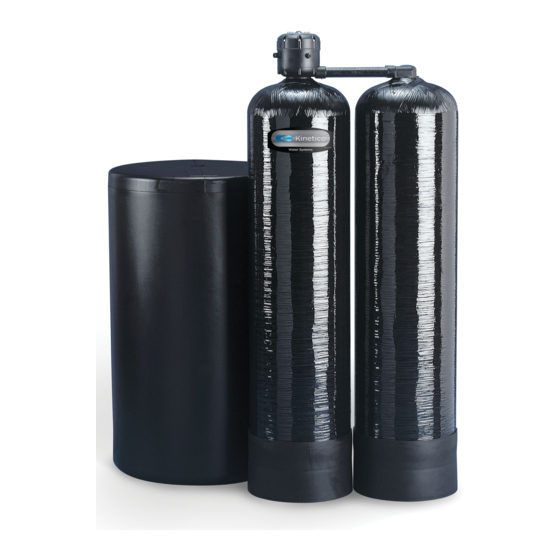
If there are any additional questions pertaining to this equipment, please contact your local Kinetico Dealer for further assistance. The Commercial Plus Series The CP Series provides continuous soft water for commercial applications. -
Page 4: System Specifications
CP Series Technical Manual Specifications Product Name CP 208s OD CP 210s OD CC 213s OD CC 216s OD Overdrive Flow (15/30 psig) 20.5 - 30.0 gpm 21.1 - 31.6 gpm 28 – 40 gpm 35.0 – 47.0 gpm Alternating Flow (15/30 psig) 11.5 - 18.0 gpm 12.0 - 19.0 gpm 20.0 - 30.0 gpm... -
Page 5: Disc Selection
CP Series Technical Manual Sizing Continuous Service Flow Charts Not recommended for 24-hour continuous flow. Caution when applying in applications requiring 24-hour continuous flow. Recommended for 24-hour continuous operation. CP208s OD mg/l 17.7 17.1 16.5 15.9 15.3 14.8 14.2 13.6 12.4 11.8 11.2... - Page 6 CP Series Technical Manual CP210s OD mg/l 1231 42.4 1214 41.8 1197 41.2 1180 40.6 1163 1146 39.5 1129 38.9 1112 38.3 1094 37.7 1077 37.1 1060 36.5 1043 35.9 1026 35.3 1009 34.8 34.2 33.6 32.4 31.8 31.2 30.6 29.5 28.9 28.3...
- Page 7 CP Series Technical Manual CP213s OD mg/l 29.5 28.9 28.3 27.7 27.1 26.5 25.9 25.3 24.8 24.2 23.6 22.4 21.8 21.2 20.6 19.5 18.9 18.3 17.7 17.1 16.5 15.9 15.3 14.8 14.2 13.6 12.4 11.8 11.2 10.6 99 103 106 110 114 118 122 125 129 Continuous Flow Rate December 15, 2004 General Information...
- Page 8 CP Series Technical Manual CP216s OD mg/l 29.5 28.9 28.3 27.7 27.1 26.5 25.9 25.3 24.8 24.2 23.6 22.4 21.8 21.2 20.6 19.5 18.9 18.3 17.7 17.1 16.5 15.9 15.3 14.8 14.2 13.6 12.4 11.8 11.2 10.6 10 11 12 13 14 15 16 17 22 23 24 25 26 27 28 29 30 12 16 19 38 42 46 50 53 57 61 65...
-
Page 9: Equipment Specifications
YSTEM PERATION Kinetico Water Conditioners use a twin tank design to assure that treated water is always available. When one tank regenerates, the other supplies treated water. The Kinetico Valve, controls when each tank is in service, when each tank must be regenerated and the regeneration of each tank. -
Page 10: Water Meter Disc
CP Series Technical Manual Water Meter Disc The frequency of regeneration can be adjusted without re-gearing the system. The use of the water meter disc provides for multiple regenerations per 360º cycle on the water meter. Each regeneration notch on a water meter disc will initiate a regeneration when the regeneration start pawl drops into one of these segments and Meter Meter... -
Page 11: Control Disc Indicator
CP Series Technical Manual Control Disc Indicator A visual indicator on top of the control disc (black dot) shows the state of the system at any time. The control disc rotates clockwise. When the indicator dot is at the 12 o'clock position, the Remote Tank is in service. -
Page 12: Additional System Components
CP Series Technical Manual System By-Pass For each system, a by-pass is recommended. This can be installed using three ball valves. This allows the system to be isolated during any service operations. By-pass valving is not included as a part of the system package. Main Remote Resin Tanks Each system uses two resin tanks. -
Page 13: Brine Tanks
CP Series Technical Manual Brine Tank Required with a standard system is a brine make-up tank. These tanks will accommodate loading of softener grade salt and provide water to dissolve brine into a saturated liquid form. Softened water is delivered to the brine tank by the control valve during the normal regeneration sequence. -
Page 14: Getting Started
CP Series Technical Manual Getting Started The following procedures have been developed to assist during the installation of your Kinetico Softener. ALL STATE AND LOCAL PLUMBING CODES MUST BE MET, including, but not limited to: Distances that equipment should be placed from the main panel box and electrical outlets. - Page 15 NOTE: Clear area along wall where PVC drain line will be run to floor drain. Kinetico does not recommend running flexible tubing across the floor or along walls, as it may be kicked out of discharge point at floor drain, or line may become pinched resulting in improper back washing.
-
Page 16: Kinetico Cp 208 - 216 Installation
CP Series Technical Manual Kinetico Softener Installation CP 208 – CP 216 Determine location to install equipment. Make sure that the unit will be on a flat surface. Test the water to confirm unit is properly sized for installation. If sand/silt or turbidity is present, a separate prefilter should be installed. - Page 17 The CP 208 & 210 will use ½” drain line. This will eliminate chances of restrictions. Position the brine drum. In Kinetico Softeners, the brine drum mixes and stores a solution of salt or potassium chloride for regeneration of the softener media. During the brine rinse cycle, this solution is drawn from the brine drum and through the media to regenerate it.
-
Page 18: Brine Tank Adjustment
CP Series Technical Manual Adjuster Tube Setting The adjuster tube is set by cutting and removing tabs on both sides of the tube. Using a pocket-knife, cut across each tab horizontally, following the channel in the plastic, and break off each tab individually until the proper setting is reached. - Page 19 CP Series Technical Manual Installing the Brine Valve After the adjustments have been made to the adjuster tube and the float cup, the brine valve assembly must be installed in the brine drum. Locate the brine valve in the brine well so that the bent tube is along the back of the brine well away from the brine drum wall.
-
Page 20: Central Brining System Installation
CP Series Technical Manual Central Brining System Installation Use teflon tape for all threaded pipe connections For 39" and 50" Diameter Drums Assemble bulkhead fittings to brine drum as shown, with the rubber washer on the inside. Be sure the washer does not "squeeze"... -
Page 21: Troubleshooting
CP Series Technical Manual Troubleshooting Ten steps to determine the problem… 1. Gather Information Ask the customer questions. Any information obtained can reduce your time on the job. Many times the customer’s response to questions will allow you to skip directly to the next section. - Page 22 CP Series Technical Manual 4. Run a soft water faucet wide open Watch the meter disc. Is it turning? Watch the no back pawl. As the meter disc turns clockwise, the no back pawl should drop into the next tooth, preventing the meter disc from turning backwards.
- Page 23 Place the unit in service position (6 o'clock or 12 o'clock). Close the soft water side of the bypass and leave it closed for one minute. On a Kinetico bypass, turn it to the off position. Open it. Did you hear a surge of water through the valve when it was opened? If so, there is a leak somewhere in the house.
- Page 24 CP Series Technical Manual 10. Check unit shut-off The drain should be dry at the service positions (12 o'clock and 6 o'clock). An occasional drip may occur. Measure the drip rate. There should be less than 5 ml of water collected in 22 seconds.
-
Page 25: Hard Water
CP Series Technical Manual Hard Water Problem Reason Solution 1. Water meter disc Non-conforming meter drive pawl. Replace meter drive pawl. is not turning. Meter drive spring installed wrong. Reinstall meter drive spring. No back pawl not installed. Install no back pawl. Damaged tooth on the meter disc. -
Page 26: Frequent Regeneration / Backwashing
Kinetico softener works. Kinetico units. may not realize that Kinetico units can Emphasize that regeneration regenerate at any time of the day or night. is controlled by the measurement of water use rather than on an arbitrary timed basis. -
Page 27: High Salt Consumption
CP Series Technical Manual High Salt Consumption Problem Reason Solution See the section entitled Frequent See the section entitled 1. Regenerates too frequently. Regeneration. Frequent Regeneration. The brine valve is set wrong or non- Verify the brine valve setting. 2. Water level in the brine drum is too conforming. -
Page 28: Iron Bleed-Through
CP Series Technical Manual Iron Bleed-through Problem Reason Solution 1. Customer Previous iron buildup inside existing Verify that customer plumbing plumbing. plumbing after the water softener. is the problem by testing the water quality at the brine fitting with water running. 2. -
Page 29: Water Running To Drain
CP Series Technical Manual Water Running to Drain Note: With softeners and filter/softeners, start by testing the drain water. If the drain water is hard, the tank currently in service has a problem with its drain valve. If the drain water is soft, start with number 1 below. Problem Reason Solution... -
Page 30: Leaks
3. Treated water has In high TDS (1000+) applications, salt Inform the customer of the a salty taste. taste may be present due to the ion Kinetico Drinking Water exchange process or sodium chloride in System or Commercial RO the raw water. System. -
Page 31: Equipment Noise
CP Series Technical Manual Equipment Noise Problem Reason Solution 1. The unit makes a The control disc is not flat on the ceramic, Replace the control disc, squealing noise. causing the drain valve to flutter. balance piston spring and the balance piston O-ring. -
Page 32: Parts
CP Series Technical Manual PARTS Complete Valve Level One Cap Screw (8) ....1010 Cap........9044A Actuator O-Ring....1460 Actuator ......9284A Cap Seal......8628 Meter Disc 1 ...... 1504 Disc 2 ...... 1505 Disc 3 ...... 1506 Disc 4 ...... 1507 Disc 5 ...... -
Page 33: Gears
CP Series Technical Manual Nozzles Gearing Regeneration Gearing Micro Nozzle 0.05 gpm – 5 gpm ......10880 ½ Louver Nozzle 0.3 – 25 gpm ........11018 Meter Gearing Unit (gallons) ......short hand Full Louver Nozzle turbine (t) CP 208s OD CP 208s (3200) ....... s-1-5-4-P4-t CP 210s OD CC 210s (3850) ....s-7-P23-P23-P6-t CP 213s OD... -
Page 34: Level 2-6
CP Series Technical Manual Level 5 Level 2 Vent Tube ......1480 Level 2 ......8784B ....208/210 ..213/216 Drain Valve Quad Ring... 1590 ..8187A Brine Flow Control CC 208 (0.4 gpm) ..... 1036 Drain Valve w Quad..7871 ... 9749 CP 210 (0.7 gpm) ..... -
Page 35: Media Tanks, Brine Tanks, Brine Valves And Media
CP Series Technical Manual Brine Valve Media Tanks, Distributors and Riser Tubes ⅜” x ⅜” Tube Union ......9210 Upper Distributor 208/210/213 ........9251 Bent Tube (18x35 Brine Tank).... 7802 216 ..........11155 Flow Restrictor (main tank) 208/210 .......... 5567A 213/2116 ...........none Media Tank Well Cover (18x35 Brine Tank)..7815A 208 ..........1091a... - Page 36 CP Series Technical Manual OMMERCIAL manual part number: 11160a © Kinetico Incorporated, December 15, 2004 Page - 36 Parts December 15, 2004 Rev. 3...
Need help?
Do you have a question about the Commercial Plus Series and is the answer not in the manual?
Questions and answers