
Related Manuals for SMC Networks ZB Series


Summary of Contents for SMC Networks ZB Series
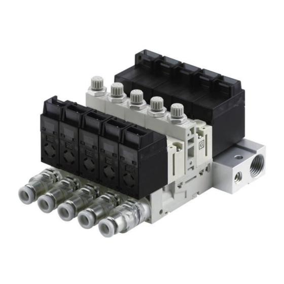
- Page 1 Doc. no. ZB-OM00201-B PRODUCT NAME Compact Vacuum Unit Ejector/ Vacuum Pump System MODEL / Series / Product Number ZB Series...
-
Page 2: Table Of Contents
Doc. no. ZB-OM00201-B Contents Safety Instructions Model Indication and How to Order Names of parts of product Mounting and Installation Air Supply Supply Pressure Piping Handling of the V Port Assembly Solenoid Valve Construction Maintenance Replacement Procedure for Filter Element Replacement Procedure for Silencer Replacement Procedure for Solenoid Valve (Supply Valve, Release Valve) Manifold Products... -
Page 3: Safety Instructions
Doc. no. ZB-OM00201-B Safety Instructions These safety instructions are intended to prevent hazardous situations and/or equipment damage. These instructions are categorized into three groups, "Caution", "Warning" and "Danger" depending on the level of hazard and damage, and the degree of emergency. They are all important notes for safety and must be followed in addition to International Standards (ISO/IEC), Japan Industrial Standards (JIS) and other safety regulations... - Page 4 Doc. no. ZB-OM00201-B Safety Instructions Caution 1. The product is provided for use in manufacturing industries. The product herein described is basically provided for use in manufacturing industries. If the product is being considered for use in other industries, consult SMC beforehand and exchange specifications or a contract if necessary.
- Page 5 Doc. no. ZB-OM00201-B ■Explanation of Symbols S ym b o l Definition Things you must not do. Instructions are provided as a drawing or sentence next to the symbol. Things you must do Instructions are provided as a drawing or sentence next to the symbol. ■Operator 1.
- Page 6 Doc. no. ZB-OM00201-B ■Safety Instructions Warning Do not disassemble, modify (including the replacement of board) or repair other than instructed in this manual. Otherwise, an injury or failure can result. Disassembly prohibited Do not operate the product outside of the specifications. Do not use for flammable or harmful fluids.
- Page 7 Doc. no. ZB-OM00201-B Caution Do not touch the terminals and connectors while the power is on. Otherwise electric shock, malfunction or damage to the switch can result. Do not touch Perform sufficient trial run. Otherwise, injury or damage to the system can result due to suction failure depending on the conditions of the suction of the workpiece or the pressure switch settings.
- Page 8 Doc. no. ZB-OM00201-B ● Product handling Installation - Tighten to the specified tightening torque. If the tightening torque is exceeded, the mounting screws, brackets and the product can be broken. Insufficient torque can cause displacement of the product from its proper position and loosening of the mounting screws. - If a commercially available switching power supply is used, be sure to ground the frame ground (FG) terminal.
- Page 9 Doc. no. ZB-OM00201-B Operating environment - Do not use in an environment where corrosive gases, chemicals, sea water, water or steam are present. These may cause failure or malfunction. - Do not use the product in a place where the product could be splashed by oil or chemicals. If the product is to be used in an environment containing oils or chemicals such as coolant or cleaning solvent, even for a short time, the solenoid valve or pressure switch/sensor may be adversely affected (damage, malfunction, or hardening of the lead wires).
- Page 10 Doc. no. ZB-OM00201-B Maintenance - Turn off the power supply, stop the supplied air, exhaust the residual compressed air in the piping and verify the release of air before performing maintenance. There is a risk of unexpected malfunction of component. - Perform regular maintenance and inspections.
-
Page 11: Model Indication And How To Order
Doc. no. ZB-OM00201-B Model Indication and How to Order ■Model Indication of the Single Unit Vacuum pump system Ejector system (1) Nozzle size Applicable supply valve and Nominal standard supply pressure Symbol nozzle Large flow Latching size (N.C.) ― ― Note 1) ●... - Page 12 Doc. no. ZB-OM00201-B (3) Exhaust type Vacuum pump system (without silencer) Exhaust through silencer (Individual exhaust) Exhaust through port (M5, individual exhaust) Note 3) (4) Combinations of the supply valve and the release valve Applicable body type Release Symbol Supply valve Ejector Pump system valve...
- Page 13 Doc. no. ZB-OM00201-B Note 6) (7) Manual override Non-locking push type Locking type (Tool required) Semi-standard Note 6) Latching type (supply valve) has the push-lock type only, but either the push type or the lock type can be selected for the release valve.
- Page 14 Doc. no. ZB-OM00201-B Note10) Note 11) (10) Vacuum (V) port Straight type2 One-touch tube fitting Metric size Straight type 4 One-touch tube fitting Straight type 1/8” One-touch tube fitting Inch size Straight type 5/32” One-touch tube fitting Elbow type ...
- Page 15 Doc. no. ZB-OM00201-B ■Model Indication for Manifold (1) Number of stations 1 station 2 stations 12 stations Note 1) (2) Pressure sensor/Vacuum pressure switch mountable Sensor/ switch non-mountable base Sensor/ switch mountable base Note 1) Select “S” when the model with either the pressure sensor or the pressure switch for vacuum is selected for how-to-order for the single unit (8).
- Page 16 Doc. no. ZB-OM00201-B ■Supply Port Ports are provided on the left and right sides of the manifold base when looking from the V port side. When it is used with the air supply only from one side, a plug to close the unused port is necessary. Purchase a plug suitable for the port size selected, and mount it to the unused port.
-
Page 17: Names Of Parts Of Product
Doc. no. ZB-OM00201-B Names of Parts of product ■Names of Individual Part Manifold Supply valve Vacuum break flow adjusting needle Vacuum break flow needle Release valve Supply valve manual override Mounting hole Filter vessel (on both sides) Filter case Vacuum (V) port Manifold base Common supply (PV) (on both sides) - Page 18 Doc. no. ZB-OM00201-B ■Summary of product elements Lead wire with connector Connecting terminal Output(OUT1)display(Green) Output(OUT1)display(Red) button (SET) LED display button(UP) button(DOWN) Output Turns on when the switch output (OUT1) is on. (OUT1) Output Turns on when the switch output (OUT2) is on. (OUT2) Displays the current status of pressure, setting mode and error code.
-
Page 19: Mounting And Installation
Doc. no. ZB-OM00201-B Mounting and Installation Note the following points when mounting and installing the product. ■ Common Precautions for Mounting and Installation (1) It is necessary to perform maintenance and replacement of the suction filter regularly to maintain the proper operation of the ejector and vacuum pump system. - Page 20 Doc. no. ZB-OM00201-B (3) Secure the space for connecting piping on the supply side when installing the product. Mounting with a bracket for single unit (Width of the bracket: 1mm) KQ2L04-M5N PD port PV port Mounting on the wall and the port released to the atmosphere at the bottom KQ2L04-M5N KQ2H04-M5N KQ2W04-M5N...
-
Page 21: Air Supply
Doc. no. ZB-OM00201-B ■Mounting and Installation of an Ejector of Manifold Specification When mounting the manifold base, it is recommended to mount a spacer on the filter case side in order to make it easier to perform maintenance service of the filter element. (Width of the manifold base mounting hole: 11.6mm) Mounting hole (on both sides) -
Page 22: Supply Pressure
Doc. no. ZB-OM00201-B Supply Pressure ■Use the product within the specified supply pressure range. Operation over the specified supply pressure range can cause damage to the product. Especially for the vacuum pump system with nozzle type pad, the pressure inside the product can increase due to the release pressure. -
Page 23: Handling Of The V Port Assembly
Doc. no. ZB-OM00201-B ■ Piping to the Vacuum (V) Port (1) Allow a sufficient margin of tube length when piping, in order to prevent twisting, tensile, moment loads, vibration or impact being applied to the tubes and fittings. This can cause damage to the tube fittings and crushing, bursting or disconnection of tubing. (2) Piping to the product is assumed to be static piping. - Page 24 Doc. no. ZB-OM00201-B When mounting the V port assembly again after it is removed, confirm that the filter case gasket is inserted properly into the groove on the body side. If the filter case gasket is out of position, vacuum may leak or the V port assembly may come off. V port assembly (Attachable/detachable without a tool) Filter case gasket...
- Page 25 Doc. no. ZB-OM00201-B Make sure the O-rings of the One-touch fittings are free from scratches and dust. Scratches or dust may result in air and vacuum leakage. When pulling the straight type tube fitting assembly away from the V port assembly, remove the clip, then connect a tube or a plug to the One-touch fitting and pull it out holding the tube or plug.
- Page 26 Doc. no. ZB-OM00201-B ■One-touch Fittings Precautions 1. Insertion of tube 1) Cut the tube perpendicularly, being careful not to damage the external surface. Use SMC’s tube cutter TK-1, 2 or 3 for cutting. Do not cut the tube with pliers, nippers, scissors, etc. If the tube is cut by any tools other than a tube cutter, the cut surface of the tube will be slanted or flat, making it difficult to be connected securely, causing the tube to come off or air leakage after the tube is connected.
-
Page 27: Solenoid Valve
Doc. no. ZB-OM00201-B Solenoid Valve ■ Manual Override Non-locking push type (Tool required) Vacuum for the ejector or the vacuum pump system is generated or released by manual operation. Use the manual override after confirming It is turned ON by pressing the manual that there is no danger. - Page 28 Doc. no. ZB-OM00201-B ■ How to Use Plug Connector Connection and removal of the connector - To attach a connector, hold the lever and connector unit between your fingers and Connector adaptor insert straight onto the pins of the connector adapter so that the lever’s pawl is pushed Cover Connector...
- Page 29 Doc. no. ZB-OM00201-B Wiring Specifications - The lead wire of the solenoid valve is connected as shown below. Connect each wire to the corresponding wire of the power supply. Simultaneous energization protection circuit Lead wire color Lead wire color Black Black Reset White...
- Page 30 Doc. no. ZB-OM00201-B ■ How to operate the supply valve of the latching type Latching type refers to a solenoid with a self holding mechanism. It has a construction whereby the moving armature in the solenoid holds the set position and the reset position during momentary energizing (10ms or longer).
-
Page 31: Construction
Doc. no. ZB-OM00201-B Construction ■Construction of ZB Series Single unit/With vacuum pressure switch Manifold/With pressure sensor Components Item Main parts material Remarks Valve body assembly Resin/HNBR Solenoid valve mounting part For adjusting release flow, with lock nut retaining Needle assembly... -
Page 32: Maintenance
Doc. no. ZB-OM00201-B Maintenance ■ Implement the maintenance and check shown below in order to use the ejector and the vacuum system safely and in an appropriate way for a long period of time. 1 Maintenance should be performed according to the procedure indicated in the Operation Manual. Improper handling can cause damage and malfunction of equipment and machinery. - Page 33 Doc. no. ZB-OM00201-B ■ Replacement Parts Description Model Remarks [Application] N.C. : Supply valve for ejector ZB1-VQ110U-□□□ (Applicable nozzle sizes: 0.3, 0.4, 0.5, 0.6) Supply valve Latching : Supply valve for ejector [Generates vacuum.] ZB1-VQ110L-□□□ (Applicable nozzle sizes: 0.3 and 0.4) ZB1-VQ120U-□□□...
- Page 34 Doc. no. ZB-OM00201-B ■Model Indication of the Replacement Parts (7) Supply valve, (8) Release valve Rated voltage 24 VDC 12 VDC Note 1) Electrical entry L plug connector with lead wire L plug connector without lead wire Note 2) M plug connector with lead wire Note 2) M plug connector without lead wire Note 1) All with light and surge suppressor.
- Page 35 Doc. no. ZB-OM00201-B ● Part No. for the connector assembly and accessories Table 2. Part No. for connector assembly Lead wire length (mm) Applicable supply/ release valve (DC + common, single) (DC + common, latching) Table 3. Accessories to supply valve/ release valve Model Accessories ZB1-VQ110U-□□...
- Page 36 Doc. no. ZB-OM00201-B (10) One-touch tube fitting (10 in one set) Body type Port size 2 One-touch tube fitting Straight Elbow Metric size 4 One-touch tube fitting 1/8” One-touch tube fitting Inch size 5/32” One-touch tube fitting * For the combination of the elbow type body and the One-touch tube fitting 4, add the suffix “-N” to the part number. KJL04-C1-N (11) Filter element (10 in one set)
-
Page 37: Replacement Procedure For Filter Element
Doc. no. ZB-OM00201-B (14) Pressure switch assembly for vacuum If only the lead wire with connector is required order part number ZS-39-5G. Lead wire with connector Rated pressure range Lead wire with connector Lead wire with connector (lead wire length: 2m) Output specifications NPN open collector 2 outputs PNP open collector 2 outputs... -
Page 38: Replacement Procedure For Silencer
Doc. no. ZB-OM00201-B ■Replacement procedure for silencer* - Turn the body upside down. Apply a watchmaker’s screw driver or your finger to the notch, and slide the silencer cover in the direction indicated by the △ mark. - When it clicks, the hook is disconnected. Put your Pry up and remove part A, cover. - Remove the silencer by using a watchmaker’s screw driver. -
Page 39: Replacement Procedure For Solenoid Valve (Supply Valve, Release Valve)
Doc. no. ZB-OM00201-B ■Replacement procedure for solenoid valve (supply valve, release valve) -This product has a "supply valve“ for generating Valve body vacuum and a “release valve” for breaking vacuum. Mounting screw Follow the procedure below to replace the solenoid valves after the product has been used for a long period of time or malfunctions. -
Page 40: Manifold Products
Doc. no. ZB-OM00201-B Manifold Products ■Increasing and Decreasing the Number of Manifold Stations - When decreasing the number of manifold stations, order the manifold base (a) exclusive for the required number of stations. When increasing the number of stations, order the required number of single units of the body type 3 valve (b). -
Page 41: Filter Case
Doc. no. ZB-OM00201-B Filter Case ■Special transparent filter case made of nylon Do not use in an environment where chemicals such as alcohol are present and where they could stick to the filter case. Vacuum Break Flow Adjusting Needle ■Vacuum break flow characteristics The graph on the right shows the flow characteristics with various supply pressures when the vacuum break flow adjustment needle is opened from the fully close... -
Page 42: Specifications
Doc. no. ZB-OM00201-B Specifications ■General Specifications Ambient -5 to 50 C (No condensation) temperature range Fluid Air, inert gas Vibration 30m/s (Without pressures sensor/vacuum pressure switch, With pressure sensor) Note 1) resistance 20m/s (With switch) Impact pressures 150m/s (Without sensor/vacuum pressure switch, With pressure sensor) Note 2) resistance 100m/s... - Page 43 Doc. no. ZB-OM00201-B ■Specifications for Supply Valve and Release Valve Supply valve Release valve Type Large flow type Latching type Standard type Part No. of ZB1-VQ110U-□ ZB1-VQ120U-□ ZB1-VQ110L-□ ZB1-VQ110-□ Supply valve and release valve Ejector Pump system Ejector Ejector (N.C.) Applicable system Note 1) (N.C)
- Page 44 Doc. no. ZB-OM00201-B ■Suction Filter Specifications Filtration rating 30μm Filtration area 130㎜ ■Pressure sensor specifications/ ZB1-PS□-A Model ZB1-PS1-A ZB1-PS3-A (Sensing part: Standard (PSE541) (PSE543) model) Rated pressure range 0 to -101kPa -100 to 100kPa Proof pressure 500kPa Output voltage 1 to 5V DC Approx.
- Page 45 Doc. no. ZB-OM00201-B ■Pressure switch for vacuum/ZB1-ZS□□□□-A Model ZB1-ZSE□□□-A ZB1-ZSF□□□-A ( ZSE10) ( ZSE10F) (Sensing part: Standard model) Rated pressure range 0 to -101kPa -100 to 100kPa Set pressure range/ 10 to -105kPa -105 to 105kPa Pressure display range Proof pressure 500kPa Min.
- Page 46 Doc. no. ZB-OM00201-B ■Internal circuit and wiring examples Pressure sensor Brown DC (+) Black OUT (Analog output) Load Blue DC (-) Voltage output type 1 to 5V Output impedance approx. 1k Vacuum pressure switch NPN (2 outputs) PNP (2 outputs) Brown DC (+) Brown DC (+) Black...
-
Page 47: Circuit Diagram
Doc. no. ZB-OM00201-B Circuit Diagram ■Specifications of a Single Unit With supply valve/release valve, without pressure sensor/vacuum pressure switch Ejector PV=PD Vacuum pump system PVPD ZB□11-K1□□□-□ ZB0020-K1□□□-□ Atmospheric vent port Atmospheric vent port Supply valve Supply valve Release valve Release valve Supply valve only, Without pressure sensor/ vacuum pressure switch Ejector PV only Vacuum pump system PV only... - Page 48 Doc. no. ZB-OM00201-B ■Manifold Specifications With supply valve/ release valve, Without pressure sensor/ vacuum pressure switch Ejector PV=PD *ZB□31-K1□□□-□ ZZB□-□□ Station D side U side Atmospheric vent port Atmospheric vent port Supply valve Supply valve Release Release valve valve With supply valve/ release valve, with vacuum pressure switch Ejector PVPD *ZB□31-Q1□L□(O)□...
-
Page 49: Weight
Doc. no. ZB-OM00201-B Weight ■Weight of a Single Unit Model of a single unit Weight g ZB□1/2□-K1□ (Single unit without sensor) ZB□3□-K1□ (One station for manifold without sensor) ■Pressure Sensor, Vacuum pressure switch Model of pressure sensor and vacuum pressure switch Weight g ZB1-PS□-A (Weight excluding the cable) ZB1-ZS□□□-A... -
Page 50: Exhaust Characteristics And Flow Characteristics Of Ejector
Doc. no. ZB-OM00201-B Exhaust Characteristics and Flow Characteristics of Ejector ■Nozzle I.D. 0.3 Supply Valve: Large Flow Type (N.C.)/ZB03□□-K1/J1 Flow characteristics Exhaust characteristics (Characteristics when the supply pressure is 0.35 MPa) Vacuum pressure Air consumption Suction flow Supply pressure [MPa] Suction flow [L/min(ANR)] ■Nozzle I.D. - Page 51 Doc. no. ZB-OM00201-B ■Nozzle I.D. 0.5 Supply Valve: Large Flow Type (N.C.)/ZB05□□-K1/J1 Exhaust characteristics Flow characteristics (Characteristics when the supply pressure is 0.35 MPa) Vacuum pressure Air consumption Suction flow Suction flow [L/min(ANR)] Supply pressure [MPa] ■Nozzle I.D. 0.6 Supply Valve: Large Flow Type (N.C.)/ZB06□□-K1/J1 Exhaust characteristics Flow characteristics (Characteristics when the supply pressure is 0.5 MPa)
- Page 52 Doc. no. ZB-OM00201-B ■Nozzle I.D. 0.3 Supply Valve: Latching Type/ZB03□□-Q1/Q2 Exhaust characteristics Flow characteristics (Characteristics when the supply pressure is 0.4 MPa) Vacuum pressure Air consumption Suction flow Vacuum pressure Suction flow [L/min(ANR)] Supply pressure [MPa] ■Nozzle I.D. 0.4 Supply Valve: Latching Type/ZB04□□-Q1/Q2 Exhaust characteristics Flow characteristics (Characteristics when the supply pressure is 0.45 MPa)
-
Page 53: Flow Characteristics Of Vacuum Pump System
Doc. no. ZB-OM00201-B Flow Characteristics of Vacuum Pump System ■Vacuum Pump System/ZB00□0-K1/J1 The flow rate at the final adsorbing part can vary depending on the piping conditions to the vacuum (V) port. The following graph shows the values when the piping φ4x50mm is connected to the vacuum (V) port. Suction flow [L/min(ANR)] - 52 -... -
Page 54: Flow Characteristics Curve
Doc. no. ZB-OM00201-B Flow Characteristics Curve ■ How to read the flow characteristics curves of ejector/vacuum pump system The flow characteristics curve shows the relationship between the vacuum pressure and the suction flow of the ejector/vacuum pump system. It shows that the vacuum pressure changes when the suction flow changes. -
Page 55: Vacuum Pressure Switch Assembly
Doc. no. ZB-OM00201-B Vacuum Pressure Switch Assembly ■Handling Precautions 1) Do not drop, hit or apply excessive shock (100m/s ) to the product. The inner parts can be damaged leading to malfunction even if the sensor body is not damaged. 2) The tensile strength of the lead wire with connector is 35N. -
Page 56: Troubleshooting
Doc. no. ZB-OM00201-B Troubleshooting ■Problems when using ejector/ vacuum pump system and troubleshooting Trouble Cause Countermeasures Initial The adsorption area is too small; the Increase the lifting force. → Increase the pad diameter adsorption adsorption force is not strong → Increase the number of pads. failure enough compared with the weight of (It fails to... - Page 57 Doc. no. ZB-OM00201-B Trouble Cause Countermeasures → Reduce the internal capacity of the vacuum Adsorption Internal capacity of the circuit on response the vacuum side is too large for circuit. → Change to an ejector with larger suction flow. is not the ejector performance.
- Page 58 Doc. no. ZB-OM00201-B Trouble Cause Countermeasures → Replace the vacuum pad with a new one. Vacuum Adsorbing part has some problem, → Revise the adsorption conditions (such as failure such as deterioration of the vacuum over time pad, or leakage due to frictional compatibility of the vacuum pressure with the (absorbs wear.
- Page 59 Doc. no. ZB-OM00201-B If the countermeasures above are not effective, there may be some problem with the product. In that case, stop using the product immediately without disassembling or repairing it. If any of the examples below are applicable, there may be a problem with the product. 1) It was used with a voltage other than the rated voltage.
- Page 60 Doc. no. ZB-OM00201-B Revision history A: P.19 Recommended tube fittings P.21 Piping to the Manifold Base B: P.21 Change of description about tightening of fitting. P.38 Change of description about filter element. 4-14-1, Sotokanda, Chiyoda-ku, Tokyo 101-0021 JAPAN Tel: + 81 3 5207 8249 Fax: +81 3 5298 5362 http://www.smcworld.com Note: Specifications are subject to change without prior notice and any obligation on the part of the manufacturer.
Need help?
Do you have a question about the ZB Series and is the answer not in the manual?
Questions and answers