
Subscribe to Our Youtube Channel
Related Manuals for SMC Networks PAF3410


Summary of Contents for SMC Networks PAF3410
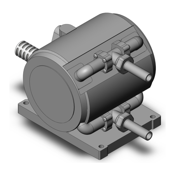
- Page 1 Doc. no. PAB-OM-H007-D PRODUCT NAME Process Pump MODEL / Series / Product Number PAF3410...
-
Page 2: Table Of Contents
Contents Safety Instructions - - - - - - - - - - - - - - - - - - - - - - - - - - - - - - - - - - - - - - - - - P.2 to 3 1. -
Page 3: Safety Instructions
Safety Instructions These safety instructions are intended to prevent hazardous situations and/or equipment damage. These instructions indicate the level of potential hazard with the labels of “Caution,” “Warning” or “Danger.” They are all important notes for safety and must be followed in addition to International ... - Page 4 Safety Instructions Caution 1.The product is provided for use in manufacturing industries. The product herein described is basically provided for peaceful use in manufacturing industries. If considering using the product in other industries, consult SMC beforehand and exchange specifications or a contract if necessary. If anything is unclear, contact your nearest sales branch.
-
Page 5: Precautions For Handling
1. Precautions for handling Warning 1) Operating environment - When dangerous fluid or fluid possibly harmful to human is used, take measure to isolate human from the pump. Should the external leakage of transported fluid come out, the serious damage to human could be caused. -
Page 6: Precautions For Installation
2. Precaution for installation Caution 1) Mounting - Only horizontal mounting is available. When the pump is not mounted horizontally with its bottom faced down, it may cause sucking failure. - Use two M5 bolts (four M6 bolts for foot bracket) to mount the pump. If the bolts are not tightened firmly, the pump could be exposed to the vibration and eventually damage. -
Page 7: Maintenance And Check
2) Adjustment of discharged flow rate (1) Use the throttle connected to discharge side to adjust discharge flow. Do not close valve suddenly, as it generates surge and remarkably shortens pump life. (2) When discharge flow is under range of specifications, keep minimum flow for process pump by installing bypass circuit from discharge side to suction side. -
Page 8: Specification And How To Order
6. Specifications and how to order ●Specifications Model PAF3410 Actuation Automatically operated Main fluid: Rc・G・NPT 3/8” Female thread, Suction/Discharge port 1/2” Tube extension, With nut (size 4, 5) Port size Pilot air: Rc, G, NPT 1/4” Supply/Exhaust port Body wetted areas... - Page 9 ●How to order Female thread, Tube piping ● Female thread Thread style Port size Symbol Style Symbol Port size Rc 03 3/8 NPT N F G P A F 3 4 1 0 ※※ B ● Option Symbol Option ● Operation type Body Symbol Operation type With foot...
-
Page 10: Discharge Capability
7. Discharge capability 1) Flow characteristic With reference to flow characteristic graph (shown below), operating condition of the pump can be set. SUP=0.5MPa 0.4MPa 0.3MPa 0.2MPa 流量(L/min) Discharge rate [L/min] Recommended typical condition A: Obtain pilot air pressure when discharge rate is 6L/min and discharge pressure is 0.25MPa. <Assumption;... - Page 11 2) Viscosity characteristic With reference to viscosity characteristic graph (shown below), discharge amount of transported fluid with higher viscosity can be calculated. 1000 粘 度(mPa・s) Viscosity (mPa・s) Recommended typical condition B: Calculate discharge amount of fluid with viscosity 100mPa・s in case of discharge rate 4.5L/min and discharge pressure 0.1MPa.
-
Page 12: Troubleshooting
8. Troubleshooting If any abnormality is found, perform check along with the following list. If the abnormality can’t be eliminated, return the pump to SMC. Warning - Exhaust dangerous fluid out of the pump before check. - Do not return the pump with dangerous fluid left. Be sure to substitute it with DI water. Otherwise, the fluid could cause burn and other damages on human during transportation. - Page 13 Trouble Possible cause Remedy ・Check valve at suction side ・Cleaning. 3) The discharge rate is insufficient. (FLUID IN) or discharge side (FLUID OUT) is clogged. ・Excessive viscosity of ・Non-conformance. Transported fluid. ・Excessive required suction or ・Reduction of required discharge pressure. head.
-
Page 14: Construction And Operating Principle
9. Construction and operating principle Air exhaust port (AIR EXH) Switching valve Air supply port (AIR SUP) Pilot valve A Pilot valve B Discharge port (FLUID OUT) Pump chamber A Pump chamber B Check valve Shaft Suction port (FLUID IN) Diaphragm A Diaphragm B Drive chamber A... -
Page 15: Sensor Mounting (Leakage Sensor)
11. Sensor mounting (leakage sensor) Series PAF can have a sensor for detecting diaphragm breakage. If fluid leaks in the pump through the diaphragm, this sensor responded it, and detects diaphragm breakage. <Mounting> 1. Remove the round head Philips screws below the AIR EXH port of the pump. Then, remove the leakage sensor cover, plug, and O-ring (Fig. - Page 16 Revision 18-Aug-2020 Revision D - Completely revised by format change. - Change the part number of amp for the sensor. 4-14-1, Sotokanda, Chiyoda-ku, Tokyo 101-0021 JAPAN Tel: + 81 3 5207 8249 Fax: +81 3 5298 5362 https://www.smcworld.com Note: Specifications are subject to change without prior notice and any obligation on the part of the manufacturer. ©...
Need help?
Do you have a question about the PAF3410 and is the answer not in the manual?
Questions and answers