
Subscribe to Our Youtube Channel
Related Manuals for SCHUNK LGP 08 - 40


Summary of Contents for SCHUNK LGP 08 - 40
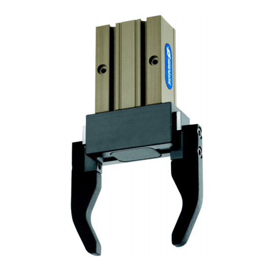
- Page 1 Translation of the original manual 2-Finger-parallel gripper LGP 08 - 40 Assembly and Operating Manual Superior Clamping and Gripping...
- Page 2 Imprint: Copyright: This manual remains the copyrighted property of SCHUNK GmbH & Co. KG. It is solely supplied to our customers and operators of our products and forms part of the unit. This documentation may not be duplicated or made accessible to third parties, in particular competitive companies, without our prior permission.
-
Page 3: Table Of Contents
8.2 The module does not travel through the entire stroke? ........20 8.3 Module opens or closes abruptly? ................. 20 8.4 Magnetic switch does not work? ................21 8.5 The gripping force drops? ..................21 8.6 Module does not achieve the opening and closing times? ........21 03.01|LGP 08 - 40|en... - Page 4 Table of contents 9 Maintenance and Care .................... 22 10 Translation of original declaration of incorporation ..........23 03.01|LGP 08 - 40|en...
-
Page 5: About This Manual
Non-compliance may cause irreversible injury or death. CAUTION Dangers for persons. Non-observance may cause minor injuries. NOTICE Information about avoiding material damage 1.1.2 Symbole Warning about a danger point Warning about hand injuries General mandatory sign to prevent material damage 03.01|LGP 08 - 40|en... -
Page 6: Variants
• LGP with gripping force maintenance device "I.D. gripping" Applicable documents • General terms of business • SCHUNK catalog gripping modules • Assembly and Operating Manuals for sensors The documents listed up here, can be download on our homepage www.schunk.com. -
Page 7: Basic Safety Notes
Link Wartungs- und Schmierin- tervalle • Make sure that the environment is free from splash water and vapors as well as from abrasion or processing dust. This ex- cludes modules that are designed specially for contaminated environments. 03.01|LGP 08 - 40|en... -
Page 8: Product Safety
2.4.3 Constructional changes, attachments, or modifications Additional drill holes, threads, or attachments that are not offered as accessories by SCHUNK may be attached only with permission of SCHUNK. Personnel qualification The assembly, initial commissioning, maintenance, and repair of the module may be performed only by trained specialist person- nel. -
Page 9: Using Personal Protective Equipment
• Perform maintenance, modifications, and additions outside the danger zone. • For all work, secure the unit against accidental operation. • Take a precautionary approach by maintenance and disassem- bly. • Only specially trained staff should disassemble the module. 03.01|LGP 08 - 40|en... -
Page 10: Variant Gripping Force Maintenance
Modules with a mechanical gripping force maintenance can, dur- ing energy supply failure, still move independently in the direc- tion specified by the mechanical gripping force maintenance. • Secure the end positions of the module with SCHUNK SDV-P pressure maintenance valves. 03.01|LGP 08 - 40|en... -
Page 11: Warranty
Type Programmable magnetic switch MMS-P • Exact type designation of the compatible sensors see ☞ catalog • If you require further information on sensor operation, contact your SCHUNK contact person or download information from our homepage. 03.01|LGP 08 - 40|en... -
Page 12: Technical Data
Max. pressure [bar] without gripping force maintenance with gripping force maintenance device Further technical data can be found in our catalog. The most re- cent version applies. 03.01|LGP 08 - 40|en... -
Page 13: Assembly
M3 / M3 / 7.4 deep M4 / M5 / M8 / 5deep 10 deep 11 deep 16 deep centering sleeve Ø5h6 / 4.35 deep Ø6h6 / Ø8h6 / Ø12h6 / 5.35 5.35 6.65 deep deep deep 03.01|LGP 08 - 40|en... -
Page 14: Air Connection
( 6, Page 12) "Technical data" Fig. 2 Air connection thread diamteter of the air connections Item connection thread diamteter of the air connections 2 x M3 2 x M5 (A = open, B = closed) G1/8" 03.01|LGP 08 - 40|en... -
Page 15: Sensors
The gripper is ready to be used with the MMS-P sensors. • If you require further information on sensor operation, contact your SCHUNK contact person or download information from our homepage. • Technical data of the sensors can be found in the data sheets (included in the scope of delivery). - Page 16 • Then, the positions of the magnetic switch have to be set Fig. 5 To relieve the cable, the electronics have to be fixed in place using cable ties (7). There are ribs (6) in place on the electronics for mounting purposes. 03.01|LGP 08 - 40|en...
- Page 17 [mm] Maß l [mm] LGP 08 15.2 24.1 LGP 20-AS 20.6 29.5 LGP 08-AS 10.1 19.0 LGP 20-IS 25.6 34.5 LGP 08-IS 18.4 27.3 LGP 25 33.6 42.5 LGP 10 18.4 27.3 LGP 25-AS 25.6 34.5 03.01|LGP 08 - 40|en...
- Page 18 (i.e. by shielding). Frequent types of disturbances are change in temperature and electro-magnetic influences. Within the closest fine-teach mode, SCHUNK cannot guarantee EMC-compatibility any more. The hysteresis adjustment is used for the manual adjustment of the switching points (if necessary).
- Page 19 4 Press the Teach-Button (4) briefly. LED 1(3) will light up twice. 5 Put the gripper to position „switch-off point of switching point 2”. Press the Teach-Button (4) briefly. LED 2 (5) will light up twice. The Mounting of the sensor MMS-P is completed. 03.01|LGP 08 - 40|en...
-
Page 20: Troubleshooting
Check the levelness of the bolting surface. Throttle check valve is missing or not set Install and adjust throttle check valve correctly Load too high Review permissible weight and length of the jaws ( 7.1, Page 13) 03.01|LGP 08 - 40|en... -
Page 21: Magnetic Switch Does Not Work
Compressed air lines between module and control valve shoud be kept as short as poss- ible Flow rate of valve is sufficiently large rela- tive to the compressed air consumption Load too high Review permissible weight and length of the jaws 03.01|LGP 08 - 40|en... - Page 22 Maintenance and Care Maintenance and Care The parallel gripper LGP is not intended for maintenance. Disassembly for maintenance or repair purposes is not possible. A damaged gripper has to be replaced completely. 03.01|LGP 08 - 40|en...
- Page 23 Bahnhofstr. 106 – 134 D-74348 Lauffen/Neckar We hereby declare that the following product: Product designation: 2-Finger-parallel gripper / LGP 08 - 40 / ID number 0312900 ... 0312917 meets the applicable basic requirements of the Machinery Directive (2006/42/EC). The incomplete machine may not be put into operation until conformity of the machine into which the incomplete machine is to be installed with the provisions of the Machinery Directive (2006/42/EC) is confirmed.
- Page 24 03.01|LGP 08 - 40|en...
Need help?
Do you have a question about the LGP 08 - 40 and is the answer not in the manual?
Questions and answers