RadioLink AT10II Instruction Manual
Adaptable to helicopter/fixed-wing/glider/multirotor/car/boat/robot(dsss&fhss)
Hide thumbs
Also See for AT10II:
- Instruction manual (88 pages) ,
- Quick start manual (12 pages) ,
- Quick start manual (3 pages)

Subscribe to Our Youtube Channel
Related Manuals for RadioLink AT10II


Summary of Contents for RadioLink AT10II
- Page 1 AT10II Instruction Manual Adaptable to Helicopter/Fixed-wing/Glider/Multirotor/Car/Boat/Robot (DSSS&FHSS) CE FCC RoHS https://www. radiolink.com Technical updates and additional programming examples available at...
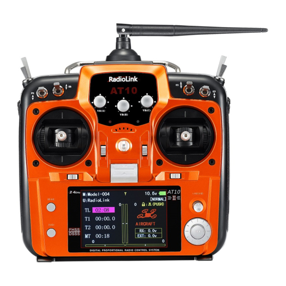
- Page 2 RadioLink Electronic Limited www.radiolink.com Thank you for purchasing RadioLink 2.4 GHz 12CH remote control system -- AT10II. This system is versatile and adaptable to various models including helicopter, fixed wing, glider, multicopter, car and boat. With the intuitive Interface and real-time telemetry, it’s suitable for both beginners and experts.
- Page 3 RadioLink Electronic Limited www.radiolink.com SAFETY PRECAUTIONS Never operate your model during adverse weather conditions. Poor visibility can cause disorientation and loss of control of your model. Never use this product in a crowd and illegal area and strictly comply with the ...
- Page 4 Versions represents the current firmware of the AT10II. Latest firmware is always available at www.radiolink.com Alarming THR POSITION! The alarm of TH-DOWN is ON by default, If the throttle channel is not at the bottom position when AT10II is switched on, there would be message of ****WARNING!!!****...
- Page 5 11 channels output PWM signal. When LED is blue/purple, SBUS and PWM signals are output synchronously. Note AT10II is default 12 channels by default and can be modified as 10 channels. When working with a non 12-channel receiver(R6DS,R6DSM,R9DS), channel quantity should be changed to 10 channels.
- Page 6 RadioLink Electronic Limited www.radiolink.com (2)SBUS&PWM dual signal output : BLUE/PURPLE led indicates SBUS&PWM signal output at the same time with 12 channels totally. The last channel of 3 pins on row 11 outputs 12 channels of SBUS signal while the other channels(3 pin from row 1 to 10, i.e CH3 to CH12) output PWM signals with 12 channels in total.
- Page 7 RadioLink Electronic Limited www.radiolink.com RSSI Testing Before flight, always remember to do the RSSI testing to avoid the possible unexpected signal loss. Power on transmitter and receiver, keep them with the distance of about 30 centimeters and both antennas straight.
Need help?
Do you have a question about the AT10II and is the answer not in the manual?
Questions and answers