Table of Contents
Advertisement
Quick Links
www.ti.com
User's Guide
DRV8410_DRV8411_DRV8411AEVM User's Guide
This document is provided with the DRV8410EVM, DRV8411EVM, and DRV8411AEVM evaluation modules
(EVM) as a supplement to the DRV8410, DRV8411, DRV8411A datasheet. This user's guide details how to
setup the EVM and install the included Graphical User Interface (GUI) program to control the motor driver.
This is a pre-production evaluation module and can differ from the final production version.
Read the user's guide before use.
Caution hot surfaces.
Contact can cause burns.
Do not touch!
1
Introduction.............................................................................................................................................................................3
1.1 Overview............................................................................................................................................................................
1.2 Features.............................................................................................................................................................................
2 Connection Descriptions.......................................................................................................................................................
Guide....................................................................................................................................................................7
3.1 Hardware Setup.................................................................................................................................................................
Installation...................................................................................................................................................................7
4 GUI Overview........................................................................................................................................................................
Modes...................................................................................................................................................................12
5.1 Stepper Motor..................................................................................................................................................................
5.2 Brushed DC Motor...........................................................................................................................................................
Figure 2-1. DRV8410EVM and DRV8411EVM Overview of Connectors and Test Points...........................................................
Figure 2-2. DRV8411AEVM Overview.........................................................................................................................................
Figure 3-1. GUI on dev.ti.com......................................................................................................................................................
Figure 3-2. GUI Installer Start Window........................................................................................................................................
Figure 3-3. Default GUI and Runtime Install Location.................................................................................................................
Figure 3-4. Window After Sucessful Installation..........................................................................................................................
Figure 4-1. DRV841xEVM GUI Home Page..............................................................................................................................
Device.......................................................................................................................................................10
SLEU121 - FEBRUARY 2022
Submit Document Feedback
ABSTRACT
CAUTION
CAUTION
Table of Contents
List of Figures
DRV8411EVM................................................................................................3
DRV8411AEVM.............................................................................................................................3
Page..........................................................................................................11
Page....................................................................................................................................12
Copyright © 2022 Texas Instruments Incorporated
Note
DRV8410_DRV8411_DRV8411AEVM User's Guide
Table of Contents
3
3
5
7
10
12
12
5
5
8
8
9
9
10
1
Advertisement
Table of Contents

Related Manuals for Texas Instruments DRV8410EVM


Summary of Contents for Texas Instruments DRV8410EVM
-
Page 1: Table Of Contents
DRV8410_DRV8411_DRV8411AEVM User's Guide ABSTRACT This document is provided with the DRV8410EVM, DRV8411EVM, and DRV8411AEVM evaluation modules (EVM) as a supplement to the DRV8410, DRV8411, DRV8411A datasheet. This user's guide details how to setup the EVM and install the included Graphical User Interface (GUI) program to control the motor driver. - Page 2 Trademarks www.ti.com List of Tables Table 2-1. Test Points and Jumpers.............................5 Trademarks All trademarks are the property of their respective owners. DRV8410_DRV8411_DRV8411AEVM User's Guide SLEU121 – FEBRUARY 2022 Submit Document Feedback Copyright © 2022 Texas Instruments Incorporated...
-
Page 3: Introduction
DRV8410EVM, DRV8411EVM, and DRV8411AEVM. The DRV8410EVM and DRV8411EVM share the same hardware (MD062) but two different BOM variants. DRV8410EVM is MD062-001 and DRV8411EVM is MD062-002. The DRV8411AEVM is it's own board design (MD063) but shares many similarities with the MD062 board. - Page 4 Test points for most important signals such as the control inputs, driver output, power supplies, LDO output, and so forth. for ease of measurement. DRV8410_DRV8411_DRV8411AEVM User's Guide SLEU121 – FEBRUARY 2022 Submit Document Feedback Copyright © 2022 Texas Instruments Incorporated...
-
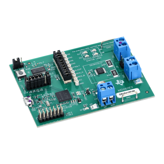
Page 5: Connection Descriptions
Connection Descriptions 2 Connection Descriptions Figure 2-1. DRV8410EVM and DRV8411EVM Overview of Connectors and Test Points Figure 2-2. DRV8411AEVM Overview Table 2-1. Test Points and Jumpers Name Description • J5: Sets action of push button (S1) – RST: MCU reset –... - Page 6 Connection Descriptions www.ti.com Table 2-1. Test Points and Jumpers (continued) Name Description • R27: Potentiometer for setting VREF voltage. DRV8410_DRV8411_DRV8411AEVM User's Guide SLEU121 – FEBRUARY 2022 Submit Document Feedback Copyright © 2022 Texas Instruments Incorporated...
-
Page 7: Evm Setup Guide
This section will provide a step-by-step guide for configuring and setting up the hardware before use. The DRV8410EVM and DRV8411EVM share the same board design but the DRV8411AEVM is slightly different than the other two boards. The hardware setup is the similar for the three boards unless it is specifically noted that it only applies to one board (the EVM name will be in paranthesis at the end of the step to note that the step only applies to that EVM). -
Page 8: Figure 3-1. Gui On Dev.ti.com
4. Read and accept the license agreement. Click "Next". 5. Keep the Application and Runtime directories to default locations. Click "Next" to install the GUI. DRV8410_DRV8411_DRV8411AEVM User's Guide SLEU121 – FEBRUARY 2022 Submit Document Feedback Copyright © 2022 Texas Instruments Incorporated... -
Page 9: Figure 3-3. Default Gui And Runtime Install Location
Figure 3-4. Window After Sucessful Installation 7. Now the GUI has been successfully installed. Section 4 provides an overview of the GUI and how to use it. SLEU121 – FEBRUARY 2022 DRV8410_DRV8411_DRV8411AEVM User's Guide Submit Document Feedback Copyright © 2022 Texas Instruments Incorporated... -
Page 10: Gui Overview
GUI Overview www.ti.com 4 GUI Overview The DRV841xEVM-GUI is design to support the DRV8410EVM, DRV8411EVM, and DRV8411AEVM. Figure 4-1 shows the home page. The GUI variant can either be DRV8410, DRV8411, or DRV8411A depending on the EVM connected. The EVM will not connect to the GUI if the wrong variant is selected. -
Page 11: Figure 4-3. Drv8410 And Drv8411 Motor Control Page
GUI Overview Figure 4-3. DRV8410 and DRV8411 Motor Control Page SLEU121 – FEBRUARY 2022 DRV8410_DRV8411_DRV8411AEVM User's Guide Submit Document Feedback Copyright © 2022 Texas Instruments Incorporated... -
Page 12: Operating Modes
J9 header. Note In parallel h-bridge mode, ensure that J7 header is shorted to connect the SENSE resistor of both h-bridges DRV8410_DRV8411_DRV8411AEVM User's Guide SLEU121 – FEBRUARY 2022 Submit Document Feedback Copyright © 2022 Texas Instruments Incorporated... - Page 13 STANDARD TERMS FOR EVALUATION MODULES Delivery: TI delivers TI evaluation boards, kits, or modules, including any accompanying demonstration software, components, and/or documentation which may be provided together or separately (collectively, an “EVM” or “EVMs”) to the User (“User”) in accordance with the terms set forth herein.
- Page 14 www.ti.com Regulatory Notices: 3.1 United States 3.1.1 Notice applicable to EVMs not FCC-Approved: FCC NOTICE: This kit is designed to allow product developers to evaluate electronic components, circuitry, or software associated with the kit to determine whether to incorporate such items in a finished product and software developers to write software applications for use with the end product.
- Page 15 www.ti.com Concernant les EVMs avec antennes détachables Conformément à la réglementation d'Industrie Canada, le présent émetteur radio peut fonctionner avec une antenne d'un type et d'un gain maximal (ou inférieur) approuvé pour l'émetteur par Industrie Canada. Dans le but de réduire les risques de brouillage radioélectrique à...
- Page 16 www.ti.com EVM Use Restrictions and Warnings: 4.1 EVMS ARE NOT FOR USE IN FUNCTIONAL SAFETY AND/OR SAFETY CRITICAL EVALUATIONS, INCLUDING BUT NOT LIMITED TO EVALUATIONS OF LIFE SUPPORT APPLICATIONS. 4.2 User must read and apply the user guide and other available documentation provided by TI regarding the EVM prior to handling or using the EVM, including without limitation any warning or restriction notices.
- Page 17 Notwithstanding the foregoing, any judgment may be enforced in any United States or foreign court, and TI may seek injunctive relief in any United States or foreign court. Mailing Address: Texas Instruments, Post Office Box 655303, Dallas, Texas 75265 Copyright © 2019, Texas Instruments Incorporated...
- Page 18 TI products. TI’s provision of these resources does not expand or otherwise alter TI’s applicable warranties or warranty disclaimers for TI products. TI objects to and rejects any additional or different terms you may have proposed. IMPORTANT NOTICE Mailing Address: Texas Instruments, Post Office Box 655303, Dallas, Texas 75265 Copyright © 2022, Texas Instruments Incorporated...
Need help?
Do you have a question about the DRV8410EVM and is the answer not in the manual?
Questions and answers