Table of Contents
Advertisement
Quick Links
OPERATOR MANUAL
CAIRE Inc.
2200 Airport Industrial Dr., Ste 500
Ball Ground, GA 30107
www.caireinc.com
Copyright © 2020 CAIRE Inc.. CAIRE Inc. reserves the right to discontinue its products, or change
the prices, materials, equipment, quality, descriptions, specifications and/or processes to its
products at any time without prior notice and with no further obligation or consequence. All
rights not expressly stated herein are reserved by us, as applicable.
MN255-1 C
Oxygen System
MODEL 4000
Advertisement
Table of Contents
Troubleshooting

Related Manuals for Saros 4000

Summary of Contents for Saros 4000
- Page 1 Oxygen System OPERATOR MANUAL MODEL 4000 CAIRE Inc. 2200 Airport Industrial Dr., Ste 500 Ball Ground, GA 30107 www.caireinc.com Copyright © 2020 CAIRE Inc.. CAIRE Inc. reserves the right to discontinue its products, or change the prices, materials, equipment, quality, descriptions, specifications and/or processes to its products at any time without prior notice and with no further obligation or consequence.
-
Page 2: Definition Of Symbols Page / Warning Page
NOTE: Indicates information considered important, but not hazard-related (e.g. messages relating to property damage). SYMBOLS USED IN THE OPERATION OF SAROS Symbols are frequently used on equipment in preference to words with the intention of reducing any possibility of misunderstanding caused by language differences. - Page 3 60 degrees from vertical. ON/OFF (Standby); Powers the device ON or OFF, but does not directly disconnect the main *Alarms for the SAROS are considered information-only signals. power. This product may be covered by one or more patents, US and inter- Increase Flow Setting;...
-
Page 4: Table Of Contents
3.1 BATTERY INSTALLATION ONTO SAROS ......................19 3.2 LOCATING THE SAROS ............................. 19 4.0 OPERATING INSTRUCTIONS .............................20 4.1 OPERATING THE SAROS FOR THE FIRST TIME ....................23 5.0 OPERATOR MAINTENANCE & SERVICE ........................26 5.1 CLEANING THE SAROS ............................ 26 5.2 ROUTINE MAINTENANCE ..........................26 5.3 CLEANING OR REPLACING AIR INLET FILTER .................... -
Page 5: Illustrations
Operator Manual ILLUSTRATIONS FIGURE 2-1. SAROS COMPONENTS ........................13 FIGURE 2-2. SAROS COMPONENTS ........................14 FIGURE 3-1. BATTERY INSTALLATION ........................19 FIGURE 5-1. BATTERY INSTALLATION ........................22 FIGURE 4-2. CANNULA INSTALLATION ......................... 23 FIGURE 5-1. SAROS COMPONENTS ........................27 FIGURE 5-2. REMOVE COVER ..........................27 FIGURE 5-3. -
Page 6: Indications For Use
A physician has prescribed a specific oxygen flow setting to meet an individual’s needs. Oxygen flow should be adjusted only under the direction of a physician. The SAROS uses a vacuum pressure adsorbent process to separate oxygen from the air and deliver oxygen rich gas to a patient through a nasal cannula. -
Page 7: Contraindications
WARNING: DO NOT DROP OR INSERT ANY OBJECTS INTO ANY OPENING ON THE DEVICE. WARNING: DO NOT BLOCK THE AIR INLET OR THE EXHAUST VENT OF THE SAROS WHEN IT IS ON A SOFT SURFACE, SUCH AS A LITTER, BED, CHAIR, CARPET, COUCH OR VEHICLE SEAT. -
Page 8: Battery Safety
OCCUR. NOTE: ONLY USE THE CAIRE INC. SUPPLIED AC POWER ADAPTER AND 24 VDC CABLE WITH THE SAROS. USE OF ANY OTHER AC POWER ADAPTER OR DC CABLE MAY BE HAZARDOUS, CAUSE SERIOUS DAMAGE TO THE SAROS AND WILL VOID THE WARRANTY. -
Page 9: Introduction
SAROS operates from external AC power, 24VDC or from a rechargeable Battery. The system includes a “Smart Battery” charger that recharges the Battery whenever the SAROS is connected to external power. The system monitors and controls both the power source and the Battery Charger. -
Page 10: Saros Oxygen System Specifications
Operator Manual 1.2 SAROS OXYGEN SYSTEM SPECIFICATIONS Dimensions • With Battery / • Without Battery 26.80” long x 4.375” diameter (68.1 cm long x 11.1 cm diameter) / 23.25” long x 4.375” diameter (59.1 cm long x 11.1 cm diameter) Weight •... - Page 11 Operator Manual Pulse Settings 16, 32, 48, 64, 80, 96 ml autoSAT Technology Servo-control to maintain consistent FiO2 Trigger Sensitivity Adjustable settings of 1 (most sensitive), 2 and 3 (least sensitive) Trigger Criteria Cannula pressure has dropped below the trigger point (typically between 0.15 – 0.45 cm of H2O of negative pressure with a MAX trigger point of .50 cm H2O) Minimum time between breaths 1.25 seconds (max 3 consecutive breaths)
- Page 12 AC Power Adapter Cord (EU) (4998-SEQ) 24 VDC Cable (9727-SEQ) Battery (9723-SEQ; reorder PN 20952897) Table 1-6. SAROS Also includes: Nasal Cannulas (2), Operator Manual, a spare HEPA and air intake filter. No additional parts required for standard operation. 12 | MN255-1 C...
-
Page 13: Introduction To Your Saros Oxygen System
2.0 INTRODUCTION TO YOUR SAROS OXYGEN SYSTEM This operator manual will inform you about the use and care of the SAROS and its standard components. Please read thoroughly all of the information in this manual before operating the SAROS and receive proper training on the use and care of this device. -
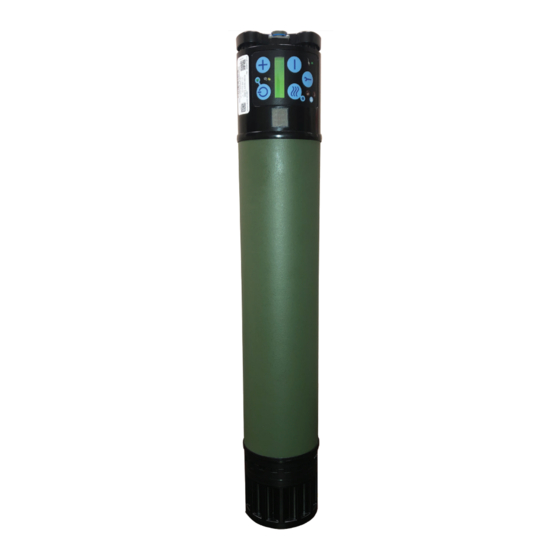
Page 14: Figure 2-2. Saros Components
Air Inlet Filter: Ambient air is drawn into the device through the air inlet located at the top of the device. This air inlet filter prevents dust / debris from entering the SAROS and should be cleaned regularly. External Power Connector: The SAROS AC Power Adapter or 24 VDC Cable connects to this receptacle. Exhaust Vent: Exhaust air from the SAROS leaves the device from this vent. -
Page 15: User Controls And System Status Indicators
The SAROS User Control Panel displays important operating information. This section will help you understand this operating information. The SAROS has two modes: Normal and Tactical. To switch between these modes, depress Utility Button, and then the Decrease Button to switch between TACT=ON and TACT=OFF. - Page 16 Operator Manual Definition of LCD display screen. Mode Battery Status Alarm Signal Mode Battery Status Blank fields indicate no battery attached. Normal mode, Pulse Dose. P indicates Normal mode. XX is the Pulse Dose value 16 to 96. Symbol indicates battery. TT is time remaining on Tactical mode, Pulse dose.
- Page 17 Operator Manual Examples of LCD display during Normal Mode with Continuous Flow Example of LCD Display indicates the following information: Normal mode, Continuous Flow at 1 LPM, no alarm, battery installed, estimated time remaining 28 minutes. Example of LCD display during Normal Mode with Pulse Flow Example of LCD Display indicates the following information: Normal mode in pulse flow setting, 96 is Pulse Dose 96 mL, BL indicates low battery alarm, battery installed, time remaining.
-
Page 18: Recommended Operating Environments
The conditions below are not part of IEC60601-1 Compliance Testing. While operating in temperatures between 0º C to 40º C, SAROS is capable of maintaining flow and purity in continuous and pulse flow modes, while operating on all power sources with the exception of Battery charging. -
Page 19: Preparation For Use And Installation
NOTE: It is important to depress the latching pin release button prior to installation. 3. Insert the Battery onto the SAROS by aligning the Battery Connector of the Battery into the connector opening at the bottom of the unit. Battery is properly engaged when the latch pin is snapped into place. -
Page 20: Operating Instructions
The device is capable of being operated directly from three different power sources: AC power adapter, DC power supply, and battery. To power the SAROS on, connect a source of power and press and hold the ON/OFF button for 2–3 seconds. - Page 21 Before using the SAROS for the first time, fully charge the Battery. Attach the Battery by aligning the connector on the battery to the mating part on the bottom of the SAROS. The Battery will click into place.
-
Page 22: Figure 5-1. Battery Installation
NOTE: It is important to depress the latching pin release button prior to installation. 3. Insert the Battery onto the SAROS by aligning the Battery Connector of the Battery into the connector opening at the bottom of the unit. Battery is properly engaged when the latch pin is snapped into place. -
Page 23: Operating The Saros For The First Time
Press and hold the “ON/OFF” Button to power ON your SAROS. The SAROS will start up in Normal Mode and Continuous Flow of 3 LPM. Allow five (5) minutes minimum for the device to reach its performance specifications. The five (5) minute warm-up time is a stabilization period during which no alerts or codes are to be expected. - Page 24 PULSE FLOW MODE FEATURES: The SAROS Pulse Flow Mode delivers a high flow oxygen bolus at the beginning of each inspiration. Your SAROS Pulse Flow Mode has a feature, called autoSAT Technology and a Pulse Flow Mode Sensitivity Setting to easily trigger the oxygen bolus delivery.
- Page 25 NOTE: You will achieve longer operating time on the Battery if you operate in the Pulse Flow Mode. Step 8: Power off the Device Press and hold the “ON/OFF” Standby Button for two (2) seconds to power OFF the SAROS. MN255-1 C | 25...
-
Page 26: Operator Maintenance & Service
THE RISK OF FIRE AND BURNS. Cleaning the SAROS Battery The Battery in the SAROS requires special care to assure a longer life and the highest level of performance. The CAIRE Inc. Battery is the only approved Battery recommended for use with the SAROS. -
Page 27: Cleaning Or Replacing Air Inlet Filter
(4770-SEQ) Instructions Label (behind) Battery Figure 5-1. SAROS Components 5.3 CLEANING OR REPLACING AIR INLET FILTER 5.3.1 Removing the air inlet cover. 5.3.2 Disconnect power supplies and remove the battery if connected. 5.3.3 Using a Phillips #1 screwdriver, loosen the four captive screws. -
Page 28: Replacing The Hepa Filter
5.3.10 Using a Phillips #1 screwdriver, re-attach the Cover with screws. 5.3.11 Initial and date the Service and Maintenance Record. Figure 5-3. Filter CAUTION: Operating the SAROS with a clogged air inlet filter may reduce performance and lead to system damage or premature failure. 5.4 REPLACING THE HEPA FILTER 5.4.1 Disconnect all power supplies including external Battery if connected. -
Page 29: Run Device And Fully Drain Saros Battery
2) Once the SAROS powers off, immediately connect to AC external power to begin re-charging the battery. You may either continue to run the SAROS or leave it powered off during re-charge. 3) Once the battery is fully charged, disconnect the battery, power off the unit if still running, and return the SAROS to proper storage conditions. 5.6 REPLACING THE 9V BATTERY 5.6.1 Disconnect power supplies and remove external battery if connected. -
Page 30: System Troubleshooting Guide
Air Inlet or HEPA Filter restricted your SAROS so there is adequate air flow. Low Oxygen Concentration Place your SAROS so that there is adequate air Inadequate Ventilation flow, i.e. not covered by a blanket or a poncho. Hot environment... -
Page 31: Alarm Indications And Codes
6.2 ALARM INDICATIONS AND CODES Priority # Alarm Signal Alarm Type Alarm Code Alarm Description Buzzer Power None 4000 Loss of Power 1 beep only Hot Unit 9510 Battery Too Hot 1 beep every 20 seconds for 120 seconds; LCD Battery Icon blinking... - Page 32 Operator Manual Priority # Alarm Signal Alarm Type Alarm Code Alarm Description Buzzer Trigger None A200 Pulse Mode Disabled due to 1 beep every 20 seconds until condition Sensor Failure clears Malfunction 952C Cannot Charge Battery 1 beep every 20 seconds until condition Battery clears 9V Low...
-
Page 33: Reprogramming/Calibration
Ensure that all recommended maintenance procedures in section 5.0 are performed while the device is in storage. It is especially important that the 3-month requirement to run the device and fully drain the SAROS battery be performed while the unit is in storage to ensure proper operation. -
Page 34: Emc Testing
10.0 EMC TESTING Guidance and Manufacturer’s Declaration —Electromagnetic Emissions The SAROS is intended for use in the electromagnetic environment specified below. The customer or the user of the SAROS should assure that it is used in such an environment. Emissions Test... - Page 35 Operator Manual Guidance and Manufacturer’s Declaration–Electromagnetic Immunity The SAROS is intended for use in the electromagnetic environment specified below. The customer or the user of the SAROS should assure that it is used in such an environment. Immunity test IEC 60601 test level Compliance level Electromagnetic environment –...
- Page 36 Recommended separation distances between portable and mobile RF communications equipment and the SAROS The SAROS is intended for use in an electromagnetic environment in which radiated RF disturbances are controlled. The customer or the user of the SAROS can help prevent electromagnetic interference by maintaining a minimum distance between portable and mobile RF communications equip- ment (transmitters) and the SAROS as recommended below, according to the maximum output power of the communications equipment.
- Page 37 Operator Manual NOTES MN255-1 C | 37...
- Page 38 Operator Manual NOTES 38 | MN255-1 C...
- Page 39 Operator Manual NOTES MN255-1 C | 39...
- Page 40 ww w. ca i re i n c.com CAIRE Inc. 2200 Airport Industrial Dr., Ste. 500 Ball Ground, GA 30107 U.S.A. Medical Product Service GmbH Borngasse 20 35619 Braunfels, Germany Tel: +49 (0) 6442-962073 Email: info@mps-gmbh.eu CAIRE and CAIRE Inc. are registered trademarks of CAIRE Inc. Please visit our website below for a full listing of trademarks.
Need help?
Do you have a question about the 4000 and is the answer not in the manual?
Questions and answers