Table of Contents
Advertisement
Quick Links
Advertisement
Table of Contents

Subscribe to Our Youtube Channel
Related Manuals for York Millennium YDAS 410


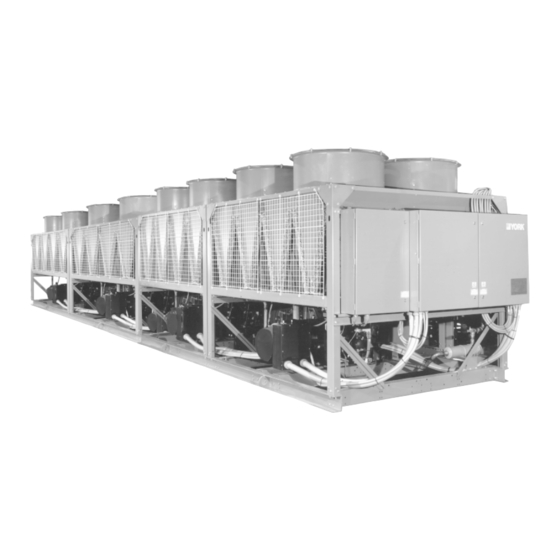
Summary of Contents for York Millennium YDAS 410
- Page 1 Millennium INSTALLATION, OPERATION, & MAINTENANCE 00064VIP ® • • SUBORDINATE...
- Page 5 00064VIP...
- Page 6 The model number denotes the following characteristics of the unit: YORK Dual Chiller Design Series Air Cooled Type Start Y = WYE-Delta X = Across-the-Line Compressor Design Series S = Screw Unit Model Voltage Code: 17 = 200-3-60 28 = 230-3-60...
- Page 7 Engineering Data (stamped on unit nameplate) denotes the following characteristics of the components of the unit: 2 Compressor “W” Chiller Refrigerant Code Configuration containing A = R-22 4 Fans & 8 Coils per Module B = R-134a 1 = 50 Hz, Economized, 1 Module 2 = 60 Hz, Economized, 1 Module 3 = 50 Hz, Economized, 1.5 Module 4 = 60 Hz, Economized, 1.5 Module...
-
Page 8: Voltage Limitations
VOLTAGE LIMITATIONS The following voltage limitations are ab- solute and operation beyond these limita- tions may cause serious damage to the compressor. VOLTAGES UNIT POWER MIN. MAX. 200-3-60 230-3-60 460-3-60 575-3-60 LD03801 MODEL YDAS COOLER CODE 410, 440, 470, 490 FIG. - Page 9 VOLTAGE LIMITATIONS The following voltage limitations are ab- solute and operation beyond these limita- tions may cause serious damage to the compressor. VOLTAGES UNIT POWER MIN. MAX. 200-3-60 230-3-60 460-3-60 575-3-60 LD03802 MODEL YDAS COOLER CODE 410, 440, 470, 490 FIG.
- Page 12 LD01604 LD01603 NOTE: Reduced clearances may be used due to jobsite restrictions. The unit will unload to prevent the condenser pressure and motor current from exceeding the maximum limits and will continue to operate without nuisance high-pressure or motor-current cutouts even though the air flow may be restricted at these conditions.
- Page 13 LD01602 LD01601...
- Page 14 LD01608 LD01607 NOTE: Reduced clearances may be used due to jobsite restrictions. The unit will unload to prevent the condenser pressure and motor current from exceeding the maximum limits and will continue to operate without nuisance high-pressure or motor-current cutouts even though the air flow may be restricted at these conditions.
- Page 15 LD01606 LD01605...
- Page 17 See power wiring schematics on pages 42 - 65. STANDARD COMPRESSOR POWER SUPPLIES WIRING TWISTED PAIR COMMUNICATION LINE (FACTORY INSTALLED, FIELD CONNECTED) UNIT PANEL (MASTER) UNIT PANEL (FOLLOWER) SYS.4 SYS.2 SYS.3 SYS.1 TERMINALS TERMINALS TERMINALS TERMINALS 1L1 1L2 1L3 1L1 1L2 1L3 SYS 4 SYS 1 POWER...
- Page 19 See power wiring schematics on pages 42 - 65. DUAL-POINT SUPPLIES OPTION TWISTED PAIR COMMUNICATION LINE (FACTORY INSTALLED, FIELD CONNECTED) UNIT PANEL (FOLLOWER) UNIT PANEL (MASTER) 1L1 1L2 1L1 1L2 SEE NOTE 8 (TYP) 230-1-50 230-1-50 CONTROL CONTROL POWER POWER SUPPLY SUPPLY COMPRESSOR...
- Page 21 See power wiring schematics on pages 42 - 65. DUAL-POINT SUPPLY WITH FACTORY-MOUNTED CIRCUIT BREAKERS TWISTED PAIR COMMUNICATION LINE (FACTORY INSTALLED, FIELD CONNECTED) SEE NOTE 8 (TYP) SEE NOTE 8 (TYP) CONTROL CONTROL POWER POWER SUPPLY SUPPLY BY OTHERS COMPRESSOR COMPRESSOR POWER POWER...
- Page 23 See power wiring schematics on pages 42 - 65. DUAL-SERVICE DISCONNECT SWITCHES OPTION TWISTED PAIR COMMUNICATION LINE (FACTORY INSTALLED, FIELD CONNECTED) UNIT PANEL (FOLLOWER) UNIT PANEL (MASTER) 1L1 1L2 1L1 1L2 SEE NOTE 8 (TYP) SEE NOTE 8 (TYP) OPTIONAL OPTIONAL CONTROL CONTROL...
- Page 24 00064VIP...
- Page 25 27507A...
- Page 26 ECONOMIZER SLIDE VALVE PIPING CONTROL SOLENOID OIL PRESSURE TRANSDUCER MOTOR TERMINAL BOX OIL INJECTION PIPING LIQUID INJECTION PIPING ECONOMIZER SERVICE 5 TON TXV VALVE MOTOR COOLING 28510A PIPING SUCTION SERVICE VALVE DISCHARGE SERVICE VALVE SUCTION PRESSURE DISCHARGE TRANSDUCER PRESSURE TRANSDUCER DISCHARGE OPTIONAL MUFFLER...
- Page 27 SUCTION PIPING DISCHARGE PIPING DISCHARGE TEMPERATURE SENSOR SLIDE VALVE SUCTION PISTON OIL SERVICE VALVE SUPPLY / VENT LINE DISCHARGE SERVICE OIL HEATER VALVE ELECTRICAL JUNCTION BOX DISCHARGE PRESSURE TRANSDUCER EVAPORATOR OPTIONAL DISCHARGE MUFFLER 28513A SYS 1 TXV SYS 1 SIGHT GLASS SYS 2 TXV SYS 1...
- Page 28 ECONOMIZER OIL SUPPLY PIPING SOLENOID OIL INJECTION PIPING OIL PRESSURE TRANSDUCER OIL SEPARATOR OIL FILTER LIQUID INJECTION PIPING 5 TON TXV MOTOR COOLING SUB COOLER PIPING (ECONOMIZER) LIQUID INJECTION SOLENOID 15 TON TXV VALVE LIQUID SUPPLY SOLENOID 5 TON TXV 15 TON TXV 28511A...
- Page 29 LIQUID STOP VALVE FILTER DRYER 28514A...
- Page 30 COMPRESSOR SIDE VIEW COMPRESSOR SIDE VIEW (MAY BE ON SIDE OR REAR OF MOTOR COVER) LD01091...
- Page 31 COMPRESSOR TOP VIEW NOTE: *On newer production chillers, this valve will not be located on the compressor. LD01092...
- Page 32 GAS OFF ECONOMIZER HEAT EXCHANGER OIL INJECTION MOTOR TERMINAL SUCTION DISCHARGE LIQUID INJECTION LD01093 FIG. 15 – COMPRESSOR GAS FLOW DIAGRAM...
- Page 33 LD01285 FIG. 16 – SCREW CHILLER REFRIGERANT FLOW DIAGRAM...
- Page 34 GENERAL Subordinate LD01095 ACTUAL ROTOR ASSEMBLY 27936A(D) FIG. 17 – COMPRESSOR ROTORS...
- Page 36 27963A...
-
Page 37: Installation
INSTALLATION WARNING To protect warranty, this equipment must be installed and serviced by an authorized YORK service mechanic or a qualified service person experienced in chiller installation. Installation must comply with all applicable codes, particularly in regard to electrical wiring and other safety elements... - Page 38 27974A COMPRESSOR VIBRATION ISOLATOR FIG. 20 – COMPRESSOR VIBRATION ISOLATOR...
- Page 39 Subordinate WARNING The Flow Switch MUST NOT be used to start and stop the chiller. It is intended only as a safety switch. Never bypass a flow switch. This will cause damage to the chiller and void any warranties.
- Page 40 LD01603 OPERATING WEIGHT DISTRIBUTION (LBS.) AND ISOLATOR LOCATION MODEL YDAS410 2043 1977 1912 1847 2085 2019 1952 1886 1713 1868 2022 2177 1749 1907 2065 2222 ISOLATOR CP-2-31 CP-2-31 CP-2-31 CP-2-31 CP-2-31 CP-2-31 CP-2-31 CP-2-31 CP-2-31 CP-2-31 CP-2-31 CP-2-31 CP-2-31 CP-2-31 CP-2-31 CP-2-31 YDAS440 2043 1977...
- Page 41 LD01607 NOTE: SI unit dimensions are in mm unless otherwise noted. OPERATING WEIGHT DISTRIBUTION (Kg) AND ISOLATOR LOCATION MODEL YDAS410 1008 ISOLATOR CP-2-31 CP-2-31 CP-2-31 CP-2-31 CP-2-31 CP-2-31 CP-2-31 CP-2-31 CP-2-31 CP-2-31 CP-2-31 CP-2-31 CP-2-31 CP-2-31 CP-2-31 CP-2-31 YDAS440 1008 ISOLATOR CP-2-31 CP-2-31 CP-2-31 CP-2-31 CP-2-31 CP-2-31 CP-2-31 CP-2-31 CP-2-31 CP-2-31 CP-2-31 CP-2-31 CP-2-31 CP-2-31 CP-2-31 CP-2-31 YDAS470 1008...
- Page 42 Terminal Block for Customer Low Voltage there are optional oil separator sump heaters which ne- (Class 2) Connections. See Note 2 cessitates using a 3KVA transformer. Terminal Block for YORK Connections Only Wiring and Components by YORK Optional Equipment Wiring and/or Components by Others...
-
Page 43: Control Power Supply
Any contacts connected to flow switch inputs or BAS in- puts on terminals 13 - 19 or TB3, or any other terminals, must be suppressed with a YORK P/N 031-00808-000 suppressor across the relay/ contactor coil which activates the contacts. CAUTION:... - Page 44 LD02051...
- Page 45 LD02052...
- Page 46 LD03094 LD03095 LD03096...
- Page 47 LD02054...
- Page 48 (Class 2) Connections. See Note 2 8. Control panel to be securely connected to earth Terminal Block for YORK Connections Only ground. Wiring and Components by YORK 9. Us 2KVA transformer in optional transformer kit un-...
- Page 49 Any contacts connected to flow switch inputs or BAS inputs on terminals 13 - 19 or TB3, or any other termi- nals, must be suppressed with a YORK P/N 031- 00808-000 suppressor across the relay/contactor coil which activates the contacts.
- Page 50 LD02066...
- Page 51 LD02067...
- Page 52 LD02066...
- Page 53 LD02069...
- Page 54 8. Control panel to be securely connected to earth (Class 2) Connections. See Note 2 ground. Terminal Block for YORK Connections Only 9. Us 2KVA transformer in optional transformer kit un- less there are optional oil separator sump heaters Wiring and Components by YORK which necessitates using a 3KVA transformer.
- Page 55 Any contacts connected to flow switch inputs or BAS inputs on terminals 13 - 19 or TB3, or any other termi- nals, must be suppressed with a YORK P/N 031- 00808-000 suppressor across the relay/contactor coil which activates the contacts.
- Page 56 LD02044...
- Page 57 LD02045...
- Page 58 LD02046...
- Page 59 LD02047...
- Page 60 (Class 2) Connections. See Note 2 8. Control panel to be securely connected to earth Terminal Block for YORK Connections Only ground. Wiring and Components by YORK 9. Us 2KVA transformer in optional transformer kit un-...
- Page 61 BAS inputs on terminals 13 - 19 or TB3, or any other ter- minals, must be sup- pressed with a YORK P/ N 031-00808-000 sup- pressor across the re- lay/contactor coil which activates the contacts.
- Page 62 LD03688...
- Page 63 LD03689...
- Page 64 LD02061...
- Page 65 LD03690...
- Page 66 28164(B)A...
- Page 67 28164(B)A Millennium Subordinate Subordinate Subordinate...
- Page 68 subordinate SUBORDINATE Subordinate Subordinate...
- Page 69 If an inductive device (relay, contactor) is supplying these contacts, the coil of the device must be suppressed with a sup- pressor YORK Part Number 031-00808-000 (60 Hz models) or a standard RC suppressor (50 Hz models) across the inductive coil.
- Page 70 Temperature Range key. The new setpoint of the device must be suppressed with a sup- will then appear. pressor YORK Part Number 031-00808-000 (60 Hz models) or a standard RC suppressor (50 NOTE: Remote Setpoint Reset will not operate when a...
- Page 71 NOTE: If the alarm circuit is applied in an application used for critical duty (such as process duty or cooling other critical equipment) and the alarm circuit should fail to function, YORK will not be liable for damages. SUBORDINATE 26001A...
- Page 72 27962A...
- Page 73 27963A 27963A NOTE: SYS 2 CONTACTORS NOT VISIBLE NOTE: SYS 1 CONTACTORS NOT VISIBLE...
- Page 74 27962A...
- Page 75 Subordinate Subordinate Subordinate Subordinate Subordinate Subordinate Subordinate LEAD SECOND THIRD COMPRESSOR COMPRESSOR COMPRESSOR SELECT...
- Page 76 28164(B)A...
- Page 77 NOTE: It is extremely important that the programmed settings correspond to the type of refrigerant used in the chiller or serious damage may occur.
- Page 78 NOTE: All programmed values and stored data, other than the internal clock time-keeping, will be maintained in memory regardless of whether the clock is on or off and regardless of the length of the power failure. NOTE: If a power failure should again occur, the above process will again need to be repeated to bring the chiller back on line.
- Page 80 NOTE: The High Motor Current Safety is a unique safety which will lock out a system after only a single fault. CAUTION: Before returning a locked out system to ser- vice, a thorough investigation of the cause of the fault should be made. Failure to re- pair the cause of the fault while manually allowing repetitive restarts may cause fur- ther expensive damage to the system.
- Page 82 NOTE: FLA (full load amps) is approximately 1.2 x RLA (rated load amps). RLA is specified on the mo- tor / chiller nameplate and is typical current de- mand under rated operating conditions in a fully loaded system. When a system is fully loaded typical motor currents may be at 60 - 85% FLA depending on operating conditions.
- Page 83 NOTE: Due to extreme operating conditions or systems where control deficiencies are present, occa- sional faults may occur with the automatic print- out. This is not a cause for concern.
- Page 84 28164(B)A subordinate...
- Page 85 NOTE: Slide valve position is approximate and should be used for reference only. Under many condi- tions, it will read well below 100%, possibly as low as 60%, when a compressor is fully loaded. NOTE: Minimum and maximum values may change as software (EPROM) revisions are made.
- Page 86 NOTE: Due to typical large variations in discharge pres- sure, a compressor running “fully loaded” may run at a wide range of currents and % FLAs. Also FLA is approximately equal to 1.2 x RLA. This means amps equal to RLA of the com- pressor will only be approximately 80% FLA.
- Page 89 26001A LD01098...
- Page 90 28164(B)A NOTE: These timers may appear not to count accord- ing to actual time. This is normal and is con- trolled by the micro to compensate for chang- ing loading requirements.
- Page 91 Subordinate subordinate Subordinate...
- Page 92 NOTE: These timers may appear not to count accord- ing to actual time. This is normal as a result of the micro’s algorithm compensating for chang- ing loading requirements.
- Page 93 Subordinate Subordinate subordinate U B O R D I N A T E subordinate Subordinate Subordinate NOTE: These timers may appear not to count accord- ing to actual time. This is normal as a result of the micro’s algorithm compensating for chang- ing loading requirements.
- Page 94 Subordinate...
- Page 97 Subordinate...
- Page 98 Subordinate...
- Page 99 Subordinate Subordinate Subordinate...
- Page 100 Subordinate...
- Page 101 OIL TEMP 122.3 DEGF LIQUID INJECTION VALVE FORWARD FANS REVERSE FANS LIQUID LINE SOLENOID RUN PERMISSIVE YORK INTERNATIONAL CORPORATION MILLENNIUM SCREW CHILLER ISN OPTION ENABLED SOFTWARE VERSION C.A12.03.01 SAFETY SHUTDOWN NUMBER 3 SHUTDOWN @ 3:33PM 01 OCT 96 SYS 1 HIGH DSCH TEMP SHUTDOWN...
- Page 102 AMBIENT AIR TEMP 70.0 DEGF LOW AMBIENT CUTOUT 25.0 DEGF LOW PRESSURE CUTOUT 44.0 PSIG LEAD SYSTEM SYS 1 LOCAL REMOTE SETTING: LOCAL SYSTEM 1 DATA COMPRESSOR STATUS RUN TIME 0- 0- 11- 1 3 D-H-M-S AVERAGE MTR = 138 %FLA PHASE L1 MTR = 145 %FLA...
- Page 103 28164(B)A...
- Page 104 28164(B)A...
- Page 105 NOTE: Under some conditions, lag compressor(s) may be started before the lead compressor reaches the required percentage of full load. This may occur if the chilled liquid is not brought to within 2°F of the control range after 5 minutes of op- eration time on the lead compressor.
- Page 106 NOTE: A lag compressor may be shut down before it is fully unloaded to avoid a Chiller fault on a Low Water Temperature cut-out under the fol- lowing conditions: a) if chilled liquid tempera- ture falls below the low end of the Control Range (CR) for more than 37 seconds, b) if chilled liq- temperature drops...
- Page 107 NOTE: Under some conditions, the lag compressor group may be sent load signals before the lead compressor reaches the required percentage of full load, if chilled liquid temperature is not brought within the control range after 10 min- utes of run time. For more details, see Section 8.2 –...
- Page 108 MIXED TEMP INDIVIDUAL PANEL RESULTING CONTROL ALGORITHM SIGNAL ACTION LOAD LOAD LOAD LOAD BALANCE BALANCE LOAD UNLOAD UNLOAD BALANCE LOAD BALANCE BALANCE BALANCE BALANCE BALANCE UNLOAD UNLOAD UNLOAD LOAD UNLOAD UNLOAD BALANCE UNLOAD UNLOAD UNLOAD UNLOAD NOTE: Failure to press the Enter key will cause the newly programmed values to be ignored and not entered into memory.
- Page 109 NOTE: A Control Range (CR) selection that is too small for the application will result in excessive com- pressor cycling or hunting of the compressor slide valves. If this situation occurs, leaving chilled liquid temperature may vary consider- ably. It is recommended that a CR of less than 3.0°F be avoided.
- Page 110 28164(B)A NOTE: The AM/PM key can only be used once here. If an error is made, press the Cancel key and begin again. NOTE: Pressing the Set Time key once enters “pro- gramming” mode in which the displayed time does not update. Pressing the Set Time a sec- ond time enters “display”...
- Page 111 NOTE: Only one start / stop time can be programmed which will apply to each of the Holiday days selected. NOTE: The AM/PM key can only be used once here. If an error is made, press Cancel and begin again. NOTE: The Holiday Schedule is only performed once, then erased from memory.
- Page 112 28164(B)A NOTE: THE PROGRAMMABLE VALUES UNDER THE PROGRAM KEY MUST BE CHECKED AND PROPERLY PROGRAMMED WHEN COM-...
- Page 113 MISSIONING THE CHILLER. FAILURE TO PROPERLY PROGRAM THESE VALUES MAY CAUSE DAMAGE TO THE CHILLER OR OP- ERATING PROBLEMS. NOTE: The type of refrigerant programmed must match the refrigerant selected on the SW1 Dip Switch on the Microprocessor Board. These selections can be viewed by pressing the Options key (see Section 3.7).
- Page 116 NOTE: Care is needed not to set the Lag Panel Start Point % too high. If this occurs, the lead group of compressors will attempt to overchill the liq- uid flowing through their evaporator below the Low Limit Water Temperature (See Section 6) to compensate for the unchilled flow through the other evaporator.
- Page 117 NOTE: Viewing % FLA or % Slide Valve of each com- pressor can often show a significant difference in the value for each compressor even though load equalization should occur. This is usually due to small pressure and mechanical variations in each system causing each compressor to load or unload a different amount with a load or un- load signal of a specific duration.
- Page 119 NOTE: It is recommended that YDAS chillers are pro- LEAD COMPRESSOR grammed for % Slide Valve control as this will COMPRESSOR COMPRESSOR SELECT provide better balancing between compressor groups. NOTE: It is often easier to select Default Setpoints and then reprogram a few that require changing rather than programming each individual value from scratch.
- Page 123 LD03803 PRESSURE PRESSURE FAN RELAY FAN RELAY 1 & 2 REV 9 & 10 REV 9M & 10M SETPOINT SETPOINT - DIFF. 9M & 10M SETPOINT SETPOINT - DIFF. (SYS 1) (SYS 3) 5 & 6 REV 13 & 14 REV 15M &...
-
Page 124: System Startup Checklist
CONTRACTOR: ___________________________ bottom or top sight glass with the com- pressor off. START-UP If it is necessary to add oil, connect a YORK oil TECHNICIAN/ pump to the charging valve on the oil separator, COMPANY: ________________________________ but do not tighten the flare nut on the delivery tub- ing. -
Page 125: Panel Checks
PANEL CHECKS Disch Press Unld = _________________ PSIG (kPa) (Power On – Both System Switches “OFF”) Avg Current Unld = _____________________ %FLA q 1. Apply 3 phase power and verify its value (See Anti Recycle Time = _____________________ Secs Fig. 20). LWT Cut-out = ________________________ °F (°C) q 2. -
Page 126: Initial Start-Up
INITIAL START-UP The subcooling temperature of each system should be calculated by recording the temperature of the liquid line After the control panel has been programmed and the at the outlet of the condenser and subtracting it from the compressor heater has been on for 24 hours prior to recorded liquid line pressure at the liquid stop valve, con- start-up, the chiller may be placed into operation. -
Page 127: Checking Economizer Superheat
q 2. Record the suction temperature, suction pres- q 1. Record the motor gas temperature, economizer sure, suction pressure converted to temperature, pressure, economizer pressure converted to and superheat of each system below: temperature, and economizer superheat below: SYS 1 SYS 2 SYS 3 SYS 4 SYS 1 SYS 2 SYS 3 SYS 4 Suction Temp = _____ _____ _____ _____ °F Motor Gas Temp = _____ _____ _____ _____ PSIG... -
Page 128: Troubleshooting
24VAC output. 4. No + 12V output (J2) from 4. Replace Power Supply Power Supply Board. Board or load on the board. NOTE: Contact YORK Service before Replacing circuit Boards! “NO RUN PERMISSIVE” 1. No chilled liquid flow. 1. Check chilled liquid flow. - Page 129 PROBLEM CAUSE SOLUTION “MOTOR CURRENT” CONTACTOR DOES FAULT NOT ENERGIZE Motor contactor may not 1. External high pressure 1. Check mechanical high energize. switch tripped. pressure cut out, fan operation, and discharge stored in memory. Forward running fans will have air flow upward. 2.
- Page 130 PROBLEM CAUSE SOLUTION “LOW SUCTION PRESSURE” 1. Improper suction pressure 1. Adjust per recommended FAULT cut-out adjustments. settings. 2. Low refrigerant charge. 2. Repair leak if necessary and add refrigerant. 3. Fouled filter dryer. 3. Change dryer core. 4. EEV defective 4.
- Page 131 PROBLEM CAUSE SOLUTION “HIGH DSCH TEMP” 1. Fault discharge temp sensor. 1. Check / replace discharge temp sensor. 2. Low oil flow to compressor. 2. Check ball valves on oil lines are open. 3. Liquid injection not working. 3. Check liquid injection. 4.
- Page 132 LOW COMPRESSOR OIL 1. Low oil charge. 1. Oil level should be LEVEL visible in either sight glass at all times. Add YORK “E” (R-22) oil if necessary. “HIGH OIL DIFFERENTIAL 1. Oil filter is dirty. 1. Change oil filter. PRESSURE” FAULT 2.
- Page 133 Should be within + or - 2 degrees. Lack of Cooling Effect 1. Fouled evaporator surface. 1. Contact the local YORK Low suction pressure service representative. will be observed. 2. Improper flow through the 2. Reduce flow to within evaporator.
- Page 134 TEMPERATURE CONVERSION TABLES The numbers in bold-face type in the center column refer to the temperature, either in Centigrade or Fahrenheit, which is to be converted to the other scale. Converting Fahrenheit to Centigrade the equivalent temperature will be found in the left column. If converting Centigrade to Fahrenheit, the equivalent temperature will be found in the column on the right.
- Page 136 36USC380 P.O. Box 1592, York, Pennsylvania USA 17405-1592 Subject to change without notice. Printed in USA Copyright © by York International Corporation 1998 ALL RIGHTS RESERVED Form 201.10-NM4 (1298) Supersedes: Nothing...
Need help?
Do you have a question about the Millennium YDAS 410 and is the answer not in the manual?
Questions and answers