
Related Manuals for York YD Series


Summary of Contents for York YD Series
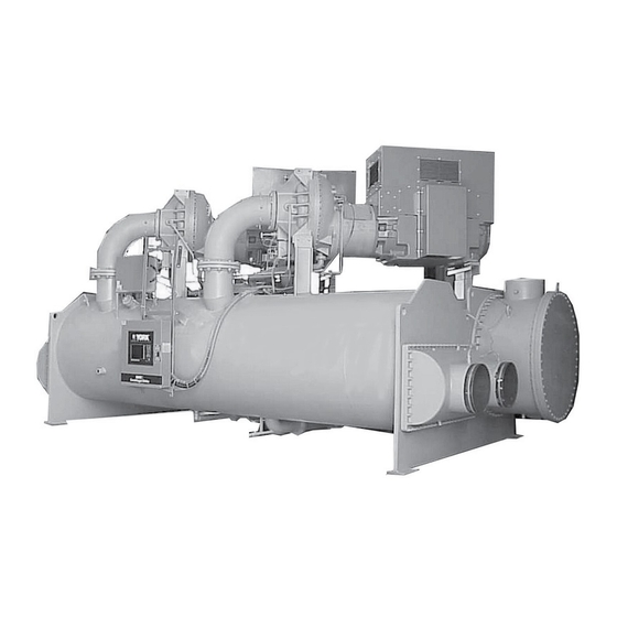
- Page 1 OPTIVIEW™ CONTROL CENTER CENTRIFUGAL LIQUID CHILLERS OPERATION Supersedes: 160.69-O1 (208) Form 160.69-O1 (912) MODEL YD (STYLE A & B) WITH OPTIVIEW™ CONTROL CENTER LD08634 R-134A Issue Date: September 30, 2012...
- Page 2 FORM 160.69-O1 ISSUE DATE: 9/30/2012 IMPORTANT! READ BEFORE PROCEEDING! GENERAL SAFETY GUIDELINES This equipment is a relatively complicated apparatus. which it is situated, as well as severe personal injury or During installation, operation maintenance or service, death to themselves and people at the site. individuals may be exposed to certain components or This document is intended for use by owner-authorized conditions including, but not limited to: refrigerants,...
- Page 3 FORM 160.69-O1 ISSUE DATE: 9/30/2012 CHANGEABILITY OF THIS DOCUMENT In complying with Johnson Controls’ policy for con- these documents, the technician should verify whether tinuous product improvement, the information con- the equipment has been modified and if current litera- tained in this document is subject to change without ture is available from the owner of the equipment prior notice.
- Page 4 FORM 160.69-O1 ISSUE DATE: 9/30/2012 NOMENCLATURE – A, B, or C DESIGN LEVEL MOTOR CODE 60 Hz 50 Hz POWER SUPPLY - for 60 Hz 5 for 50 Hz COMPRESSOR CODE J1, J2, J3, J4, J5 CONDENSER CODE XA, XB, XC, XD, YA, YB, YC, YD, ZA, ZB, ZC, ZD, AA, AB, AC, AD EVAPORATOR...
-
Page 5: Table Of Contents
FORM 160.69-O1 ISSUE DATE: 9/30/2012 TABLE OF CONTENTS SECTION 1 – DESCRIPTION OF SYSTEM AND FUNDAMENTALS OF OPERATION .......... 9 System Operation Description .......................... 9 Compressor Starting ............................10 Compressor Shutdown ........................... 14 SECTION 2 – OPTIVIEW CONTROL CENTER .....................23 Introduction .............................. - Page 6 FORM 160.69-O1 ISSUE DATE: 9/30/2012 TABLE OF CONTENTS (CONT'D) Security Log Screen ............................. 103 Security Log Details Screen ......................... 104 Custom View Screen ............................ 105 Custom View Setup ............................106 Trend Screen ..............................107 Trend Setup Screen ............................. 109 Advanced Trend Setup Screen ........................111 Common Slots Screen ..........................
- Page 7 FORM 160.69-O1 ISSUE DATE: 9/30/2012 LIST OF FIGURES FIGURE 1 - Model YD Chiller ............................9 FIGURE 2 - Chiller Operation Flow Chart .......................15 FIGURE 3 - Optiview™ Control Center ........................25 FIGURE 4 - Home Screen ............................30 FIGURE 5 - System Screen ............................33 FIGURE 6 - Evaporator Screen ..........................35 FIGURE 7 - Condenser Screen ..........................38 FIGURE 8 - Refrigerant Level Control Screen ......................40...
- Page 8 FORM 160.69-O1 ISSUE DATE: 9/30/2012 THIS PAGE INTENTIONALLY LEFT BLANK. JOHNSON CONTROLS...
-
Page 9: Section 1 - Description Of System And Fundamentals Of Operation
FORM 160.69-O1 ISSUE DATE: 9/30/2012 SECTION 1 – DESCRIPTION OF SYSTEM AND FUNDAMENTALS OF OPERATION SYSTEM OPERATION DESCRIPTION Each compressor also has a Discharge Temperature The following is a high level description of the chill- thermistor and High Pressure safety device. er control. -
Page 10: Compressor Starting
FORM 160.69-O1 SECTION 1 – DESCRIPTION OF SYSTEM AND FUNDAMENTALS OF OPERATION ISSUE DATE: 9/30/2012 The Chiller Current Limit setpoints are used to specify If equipped with the compressor Variable Geometry Diffuser (VGD), the chiller is started with the VGD in the motor current limit for the chiller as a whole. - Page 11 FORM 160.69-O1 SECTION 1 – DESCRIPTION OF SYSTEM AND FUNDAMENTALS OF OPERATION ISSUE DATE: 9/30/2012 Level Control Setpoint. This ramp allows the level to the run time of the compressors are evaluated to deter- go from the present level to the Level Control Setpoint mine which should be the Lead compressor (The one over a period programmed as the Ramp Up Time with the least amount of run time is identified as the...
- Page 12 FORM 160.69-O1 SECTION 1 – DESCRIPTION OF SYSTEM AND FUNDAMENTALS OF OPERATION SECTION 1 – DESCRIPTION OF SYSTEM AND FUNDAMENTALS OF OPERATION ISSUE DATE: 9/30/2012 compressor. The Override Time Remaining displays An LED on the Surge – Dual Compressor Setup Screen the time remaining in the “Valve Preset”...
- Page 13 FORM 160.69-O1 SECTION 1 – DESCRIPTION OF SYSTEM AND FUNDAMENTALS OF OPERATION ISSUE DATE: 9/30/2012 sor will not be brought on line. After this period has With Software version C.OPT.11.03.01.004 (or later), elapsed, the lag compressor can be brought on line per a single compressor can be locked out while both com- normal operation.
-
Page 14: Compressor Shutdown
FORM 160.69-O1 SECTION 1 – DESCRIPTION OF SYSTEM AND FUNDAMENTALS OF OPERATION ISSUE DATE: 9/30/2012 Normal Or Single Compressor Mode If the Lag compressor is taken off line due to a Low Load condition while both compressors are running (as (Software version C.OPT.11.03.01.004 (or later)) explained above), a Soft Shutdown is performed on the The COMPRESSOR MODE Setpoint, available on the... -
Page 15: Figure 2 - Chiller Operation Flow Chart
FORM 160.69-O1 SECTION 1 – DESCRIPTION OF SYSTEM AND FUNDAMENTALS OF OPERATION ISSUE DATE: 9/30/2012 YD Dual Compressor Chiller Chiller Standby Electro-Mechanical Starter Chiller Start Sequence Compressor Start Inhibit Disch Valves Closed? Chiller Start Requirement Is a Compressor in Select Lead Compressor Service Lockout Select the other Select the Compressor... - Page 16 FORM 160.69-O1 SECTION 1 – DESCRIPTION OF SYSTEM AND FUNDAMENTALS OF OPERATION ISSUE DATE: 9/30/2012 YD Dual Compressor Chiller Electro-Mechanical Starter Chiller Start Sequence 1 compressor running (from Page 1) Is La Compressor in Don't start lag compressor Service Lockout Single Compressor Mode? Lead...
- Page 17 FORM 160.69-O1 SECTION 1 – DESCRIPTION OF SYSTEM AND FUNDAMENTALS OF OPERATION ISSUE DATE: 9/30/2012 YD Dual Compressor Chiller Normal Safety Checks Electro-Mechanical Starter (Except for oil low temp Chiller Start Sequence differential) Lag Compr Startup PRVs and Start Lag Compressor From Disch Valve on Motor...
- Page 18 FORM 160.69-O1 SECTION 1 – DESCRIPTION OF SYSTEM AND FUNDAMENTALS OF OPERATION ISSUE DATE: 9/30/2012 YD Dual Compressor Chiller Electro Mechanical Chiller 2 Compressors Running Capacity Cycling (Lag Compressor Stop) Sequence (from Page 3) Has Lag Compressor Run >30 Min As motor currents fall below 50% with Motor Current two compressors running, a single...
- Page 19 FORM 160.69-O1 SECTION 1 – DESCRIPTION OF SYSTEM AND FUNDAMENTALS OF OPERATION ISSUE DATE: 9/30/2012 YD Dual Compressor Chiller Electro Mechanical Starter Chiller Soft Shutdown 2 Compressors Running 1 Compressor Running (from Page 3) (from Page 1 or 4) Chiller normal Chiller normal or cycling stop or cycling stop...
- Page 20 FORM 160.69-O1 SECTION 1 – DESCRIPTION OF SYSTEM AND FUNDAMENTALS OF OPERATION ISSUE DATE: 9/30/2012 YD Dual Compressor Chiller Electro-Mechanical Starter Chiller Fault Stop (manual or auto restart) 2 Compressors Running 1 Compressor Running (from Page 3) (from Page 1 or 4) Chiller Fault Chiller Fault Condition...
- Page 21 FORM 160.69-O1 SECTION 1 – DESCRIPTION OF SYSTEM AND FUNDAMENTALS OF OPERATION ISSUE DATE: 9/30/2012 YD Dual Compressor Chiller Anti-Surge Control Algorithm Chiller Running Two Compressor Mode. Lead Compressor controlling LChWT Lag Compressor following current of Lead Are Compressor Motor Currents Equal within 20% Are vanes on the lower current compressor open more than the...
- Page 22 FORM 160.69-O1 ISSUE DATE: 9/30/2012 THIS PAGE INTENTIONALLY LEFT BLANK. JOHNSON CONTROLS...
-
Page 23: Section 2 - Optiview Control Center
FORM 160.69-O1 ISSUE DATE: 9/30/2012 SECTION 2 – OPTIVIEW CONTROL CENTER INTRODUCTION The YORK OptiView™ Control Center is a micro- Advanced Diagnostics and troubleshooting informa- processor based control system for R134a centrifugal tion for Service Technicians are included in YORK chillers. - Page 24 Program Card. Program Cards are shirt-pocket- • xx - controls revision level (00, 01, etc) size portable memory storage devices available from YORK. This board is backward compatible • y – language package (0=English only, 1=NEMA, to YD chillers presently using the 031-01730-000 2=CE, 3=NEMA/CE ) microboard.
-
Page 25: Optiview Control Center
FORM 160.69-O1 SECTION 2 – OPTIVIEW CONTROL CENTER ISSUE DATE: 9/30/2012 OPTIVIEW CONTROL CENTER The OptiView™ Control Center display is highlighted is considered in the STOP/RESET position. When in by a full screen graphics display. This display is nested the middle position, this is considered the RUN state. within a standard keypad, and is surrounded by “soft”... -
Page 26: Interface Conventions
FORM 160.69-O1 SECTION 2 – OPTIVIEW CONTROL CENTER ISSUE DATE: 9/30/2012 INTERFACE CONVENTIONS Overview The new graphical display on each control panel al- lowed to change any values. To change any values, the lows a wide variety of information to be presented to user must return to the Home Screen (shown by de- the user. - Page 27 FORM 160.69-O1 SECTION 2 – OPTIVIEW CONTROL CENTER ISSUE DATE: 9/30/2012 use the numeric keys to enter the desired value. Free Cursor Leading zeroes are not necessary. If a decimal On screens containing many setpoints, a specific “soft” point is necessary, press the ‘•’ key (i.e. 45.0) key may not be assigned to each setpoint value. A soft key will be assigned to enable the cursor arrow keys Pressing the p key, sets the entry value to the de- below the numeric keypad which are used to “high-...
- Page 28 Motor EM Starter Version Setpoints Setup Schedule User Comms Printer Sales Order Operations Diagnostics (Refer to YORK Service Manual 160.69-M1) History History Details Security Log Screen Security Log Details Screen Custom View Custom Setup Trend Trend Setup Advanced Trend Setup...
-
Page 29: Analog Input Ranges
FORM 160.69-O1 SECTION 2 – OPTIVIEW CONTROL CENTER ISSUE DATE: 9/30/2012 ANALOG INPUT RANGES The following table indicates the valid display range for each of the analog input values. In the event that the input sensor is reading a value outside of these ranges, the <... -
Page 30: Home Screen
FORM 160.69-O1 SECTION 2 – OPTIVIEW CONTROL CENTER ISSUE DATE: 9/30/2012 HOME SCREEN Overview Motor 1 When the chiller system is powered on, the above de- Motor Run (LED) fault display appears. The primary values which must On when the digital output controlling compressor #1 be monitored and controlled are shown on this screen. - Page 31 FORM 160.69-O1 SECTION 2 – OPTIVIEW CONTROL CENTER ISSUE DATE: 9/30/2012 Message Clear Programmable Access Level Required: SERVICE Login Access Level Required: VIEW When certain safety or cycling conditions have been detected and the chiller has been shutdown, the main The OptiView™...
- Page 32 FORM 160.69-O1 SECTION 2 – OPTIVIEW CONTROL CENTER ISSUE DATE: 9/30/2012 Oil Sump Navigation System A detailed view of all the oil pump and oil sump pa- rameters. It also controls the Seal Lubrication func- Used to provide additional system information. tionality.
-
Page 33: System Screen
FORM 160.69-O1 SECTION 2 – OPTIVIEW CONTROL CENTER ISSUE DATE: 9/30/2012 SYSTEM SCREEN Overview Compressor 2 This screen gives a general overview of common chill- Discharge Temperature er parameters for both shells. Displays the temperature of the refrigerant in its gas- eous state at discharge of the compressor #2 as it trav- Display Only els to the condenser. - Page 34 FORM 160.69-O1 SECTION 2 – OPTIVIEW CONTROL CENTER ISSUE DATE: 9/30/2012 Chilled Liquid Temperature - Return Oil Sump Temperature Displays the temperature of the liquid as it enters the Displays the temperature of the oil in the sump. evaporator. Chiller Current Limit Setpoint Chilled Liquid Temperature - Setpoint Displays the active temperature setpoint to which the Displays the Chiller Current Limit Setpoint.
-
Page 35: Evaporator Screen
FORM 160.69-O1 SECTION 2 – OPTIVIEW CONTROL CENTER ISSUE DATE: 9/30/2012 EVAPORATOR SCREEN Leaving Chilled Liquid Temperature Overview This screen displays a cutaway view of the chiller Displays the temperature of the liquid as it leaves the evaporator. All setpoints relating to the evaporator side evaporator. - Page 36 Evaporator Pressure at which a the incoming setpoint is not an offset that is applied to safety shutdown is initiated. Service Technicians refer the locally programmed Base setpoint value, but rather to YORK Service Manual 160.69-M1. is the setpoint value itself. JOHNSON CONTROLS...
- Page 37 When an Evaporator Refrigerant Sensor has been in- of the Leaving Chilled Liquid Temperature control. stalled it must be enabled via this toggle before the Service Technicians refer to YORK Service Manual system will utilize the new, enhanced resolution input. 160.69-M1.
-
Page 38: Condenser Screen
FORM 160.69-O1 SECTION 2 – OPTIVIEW CONTROL CENTER ISSUE DATE: 9/30/2012 CONDENSER SCREEN Small Temperature Difference Overview This screen displays a cutaway view of the chiller con- Displays the difference between the Condenser Refrig- denser. All setpoints relating to the condenser side of erant temperature and the Leaving Condenser Liquid the chiller are maintained on this screen. - Page 39 Refrigerant Level Setpoint utilize the new, enhanced resolution input. Service Tech- nicians refer to YORK Service Manual 160.69-M1. Displays the setpoint to which the refrigerant level is being controlled.
-
Page 40: Refrigerant Level Control Screen
Displays the Zone Control State (Zone 1, Zone 2, Zone Requires a login access level of SER- 2 to Zone 1) currently in effect for the Refrigerant VICE. Service technicians refer to YORK Level Control. “Zone Control Off” is displayed when Service manual 160.69-M1 for opera- chiller is shutdown. - Page 41 FORM 160.69-O1 SECTION 2 – OPTIVIEW CONTROL CENTER ISSUE DATE: 9/30/2012 Zone Control Time Remaining [Refrigerant Level Control] Hold] (Manual) Displays the amount of time remaining in the 60-sec- This key puts the level control into manual mode and ond countdown timer when transitioning from Zone 2 sends a Hold command to the variable orifice.
-
Page 42: Main Compressor Screen
FORM 160.69-O1 SECTION 2 – OPTIVIEW CONTROL CENTER ISSUE DATE: 9/30/2012 MAIN COMPRESSOR SCREEN Overview Compressor 1 This screen displays a cutaway of the chiller compres- Oil Pressure sors, revealing the impellers. Animation of the impel- Displays the pressure differential between the Pump ler indicates when the compressor is running. - Page 43 FORM 160.69-O1 SECTION 2 – OPTIVIEW CONTROL CENTER ISSUE DATE: 9/30/2012 Discharge Temperature Programmable None Displays the temperature of the refrigerant in its gas- eous state at the discharge of the compressor #1 as it Navigation travels to the condenser. Home Discharge Superheat Access Level Required: VIEW...
-
Page 44: Compressor 1 Screen
The offset pressure calculation is not performed if ei- Requires login access level of SERVICE. ther transducer is out of range. The offset value is taken Service technicians refer to YORK Ser- as 0 PSI in this instance. If compressor #2 is already vice manual 160.69-M1 for explanation... - Page 45 FORM 160.69-O1 SECTION 2 – OPTIVIEW CONTROL CENTER ISSUE DATE: 9/30/2012 Compressor Status Pre-rotation Vanes Hold (Manual) Displays whether compressor #1 has been selected as This key puts the vanes into manual mode and applies the lead or Lag compressor. The lead compressor is se- a hold command to the vanes.
-
Page 46: Compressor 2 Screen
Requires login access level of SERVICE. subtracted algebraically from the differential pressure. Service technicians refer to YORK Ser- The offset pressure calculation is not performed if ei- vice manual 160.69-M1 for explanation ther transducer is out of range. - Page 47 FORM 160.69-O1 SECTION 2 – OPTIVIEW CONTROL CENTER ISSUE DATE: 9/30/2012 Vane Motor Switch (Open/Closed) Pre-rotation Vanes Hold (Manual) Indicates closed when the compressor #1 vanes are in This key puts the vanes into manual mode and applies the fully closed position. Otherwise, indicates open. a hold command to the vanes.
-
Page 48: Proximity Probe Calibration Screen
#1 and compressor #2. Requires a login access level of SER- Oil Pressure VICE. Service Technicians refer to YORK Displays the pressure differential between the pump oil Service Manual 160.69-M1 for opera- pressure transducer (compressor bearing input) and the tion instructions and explanation of all sump oil pressure transducer. - Page 49 Causes an instant return to the Home Screen. Cancel Calibration Compressor This option only becomes available after calibration has started. Service Technicians refer to YORK Service Return to the Compressor Screen. Manual 160.69-M1 for an explanation of this setpoint. Accept Calibration This option only becomes available after the calibra- tion sequence is complete.
-
Page 50: Pre-Rotation Vanes Calibration Screen
Cancel Calibration values. This option only becomes available after calibration has started. Service Technicians refer to YORK Service Display Only Manual 160.69-M1 for an explanation of this setpoint. Pre-Rotation Vanes Opening (LED) NAVIGATION Indicates the vanes are opening. -
Page 51: Variable Geometry Diffuser (Vgd) 1 Screen
FORM 160.69-O1 SECTION 2 – OPTIVIEW CONTROL CENTER ISSUE DATE: 9/30/2012 VARIABLE GEOMETRY DIFFUSER (VGD) 1 SCREEN Overview Pre-rotation Vanes Position (This feature applies to Software version C.MLM.11.02. Displays the position of the Pre-rotation vanes over XXX (and later) or C.OPT.11.02.300 (and later)) the range of 0% (fully closed) to 100% (fully open). - Page 52 FORM 160.69-O1 SECTION 2 – OPTIVIEW CONTROL CENTER ISSUE DATE: 9/30/2012 VGD Count [VGD] Close (Manual) Displays the number of times the Stall Detector Board This key puts the VGD in manual mode and sends a output voltage goes above the High Limit setpoint close command to the VGD.
-
Page 53: Variable Geometry Diffuser (Vgd) 2 Screen
FORM 160.69-O1 SECTION 2 – OPTIVIEW CONTROL CENTER ISSUE DATE: 9/30/2012 VARIABLE GEOMETRY DIFFUSER (VGD) 2 SCREEN Pre-rotation Vanes Position Overview (This feature applies to Software version C.MLM.11.02. Displays the position of the Pre-rotation vanes over XXX (and later) or C.OPT.11.02.300 (and later)) the range of 0% (fully closed) to 100% (fully open). - Page 54 FORM 160.69-O1 SECTION 2 – OPTIVIEW CONTROL CENTER ISSUE DATE: 9/30/2012 VGD Count [VGD] Close (Manual) Displays the number of times the Stall Detector Board This key puts the VGD in manual mode and sends a output voltage goes above the High Limit setpoint close command to the VGD.
-
Page 55: Variable Geometry Diffuser (Vgd) Setpoints Screen
2 are maintained on this screen. All setpoints re- quire a login access level of Service unless otherwise Diffuser Gap Close (LED) noted. Service Technicians refer to YORK Service Illuminates when a close signal is being applied to the Manual 160.69-M1 for operation and explanation of VGD. -
Page 56: Vgd 2
FORM 160.69-O1 SECTION 2 – OPTIVIEW CONTROL CENTER ISSUE DATE: 9/30/2012 Time Remaining Programmable PRV VGD Inhibit Displays the time remaining in the “Probe Wait Time” interval (value programmed as the Probe Wait Time (40% to 100%; default 90%). Applicable to dual com- Setpoint) while the VGD is in the Stall Waiting State pressor operation only. -
Page 57: Vgd 1
FORM 160.69-O1 SECTION 2 – OPTIVIEW CONTROL CENTER ISSUE DATE: 9/30/2012 Extreme Stall Duration Low Limit (10 to 20 minutes; default 10) – This setpoint applies (0.4-0.8vdc; default 0.6) – in the Stall Reacting State, to both VGD controls. This setpoint specifies the maxi- the VGD is driven closed until the Stall Detector Board mum allowed time an extreme stall condition can exist output voltage decreases to this level. -
Page 58: Variable Geometry Diffuser (Vgd) 1 Calibration Screen
Start Calibration programmable setpoints and displayed values. Initiates the calibration start. Service Technicians refer to YORK Service Manual 160.69-M1 for calibration Display Only procedure. Diffuser Gap Open (LED) Cancel Calibration Illuminates when an open signal is being applied to the VGD. -
Page 59: Variable Geometry Diffuser (Vgd) 2 Calibration Screen
Start Calibration programmable setpoints and displayed values. Initiates the calibration start. Service Technicians refer to YORK Service Manual 160.69-M1 for calibration DISPLAY ONLY procedure. Diffuser Gap Open (LED) Cancel Calibration Illuminates when an open signal is being applied to Cancels a calibration sequence that is in progress. -
Page 60: Hot Gas Bypass Screen
Delta P/P Requires access level of SERVICE. Ser- A parameter that represents system differential or vice Technicians refer to YORK Service “Head”. It is calculated as [(condenser pressure – Manual 160.69-M1 for operation instruc- evaporator pressure) / evaporator pressure] tions and explanation of all program- mable setpoints and displayed values. - Page 61 Hot Gas Bypass Control Mode Maximum Open Indicates whether the Hot Gas Bypass is under automat- Service Technicians refer to YORK Service Manual ic, manual or override control. “Override” is displayed 160.69-M1. during Minimum Load override conditions or when the...
-
Page 62: Surge Protection Screen
FORM 160.69-O1 SECTION 2 – OPTIVIEW CONTROL CENTER ISSUE DATE: 9/30/2012 SURGE PROTECTION SCREEN Surge Window Count Overview This screen displays both single compressor and dual Displays the number of single-compressor surge events compressor surge protection parameters. An LED il- that have occurred in the last 1 to 5 minutes (as pro- luminates when a surge event is detected. - Page 63 FORM 160.69-O1 SECTION 2 – OPTIVIEW CONTROL CENTER ISSUE DATE: 9/30/2012 Dual Compressor Operation Lead Pre-rotation Vanes Position Surge Window Time Displays the position of the lead compressor pre-rota- tion vanes position When the lag compressor is started, this value counts Lead Variable Geometry Diffuser Position up from 1 minute to the time programmed as the COUNT WINDOW Setpoint.
-
Page 64: Surge Protection Screen (Single-Compressor Operation)
FORM 160.69-O1 SECTION 2 – OPTIVIEW CONTROL CENTER ISSUE DATE: 9/30/2012 SURGE PROTECTION SCREEN (SINGLE-COMPRESSOR OPERATION) Surge Window Time Overview This screen displays the single-compressor surge pro- When the chiller enters run mode, this value counts tection parameters. The setpoints applicable to this up to the time programmed as the COUNT WINDOW feature are maintained here. - Page 65 FORM 160.69-O1 SECTION 2 – OPTIVIEW CONTROL CENTER ISSUE DATE: 9/30/2012 Surge Detected (LED) the SHUTDOWN setpoint is Enabled, and the SURGE WINDOW COUNT exceeds the COUNT LIMIT at Illuminates for 5 seconds each time a surge is detected. the completion of this period, a safety shutdown is performed and “Surge Protection –...
- Page 66 FORM 160.69-O1 SECTION 2 – OPTIVIEW CONTROL CENTER ISSUE DATE: 9/30/2012 • If both the SHUTDOWN and EXTENDED RUN Navigation setpoint are Enabled, the 10 minute Extended Home RUN mode is invoked as described above. How- Access Level Required: VIEW ever, if the SURGE WINDOW COUNT exceeds the COUNT LIMIT at the completion of the 10 Causes an instant return to the Home Screen...
-
Page 67: Surge Protection Screen (Dual-Compressor Operation)
FORM 160.69-O1 SECTION 2 – OPTIVIEW CONTROL CENTER ISSUE DATE: 9/30/2012 SURGE PROTECTION SCREEN (DUAL-COMPRESSOR OPERATION) Overview Surge Window Count This screen displays the dual-compressor surge protec- Displays the number of dual-compressor surge events tion parameters. The setpoints applicable to this feature that have occurred in the last 15 to 120 minutes (as are maintained here. - Page 68 FORM 160.69-O1 SECTION 2 – OPTIVIEW CONTROL CENTER ISSUE DATE: 9/30/2012 Lead Compressor Count Limit Access Level Required: OPERATOR Identifies the compressor that has been assigned as the lead compressor. Allows the user to define the maximum number of surge events (2 to 8; default 3) that can occur within Lead % Full Load Amps the programmed Count Window period of time before the lag compressor is taken off line.
-
Page 69: Capacity Compressor Cycling Screen
FORM 160.69-O1 SECTION 2 – OPTIVIEW CONTROL CENTER ISSUE DATE: 9/30/2012 CAPACITY COMPRESSOR CYCLING SCREEN Overview Lead % Full Load Amps This screen allows the user to specify the chiller load Displays the motor current of the lead compressor as conditions under which the lag compressor is cycled on a percentage of the full load amps of that compressor and off. - Page 70 FORM 160.69-O1 SECTION 2 – OPTIVIEW CONTROL CENTER ISSUE DATE: 9/30/2012 Lead Compressor sor is brought on line. “Checking Minimum Rate” is displayed after the Pulldown Delay is finished and until Identifies the compressor that has been assigned as the either the Delta T Rate is less than the Minimum Rate lead compressor.
- Page 71 FORM 160.69-O1 SECTION 2 – OPTIVIEW CONTROL CENTER ISSUE DATE: 9/30/2012 However, the oil pressure transducer Auto-zeroing is Programmable not performed. The offset calculations done during the Minimum Rate and Minimum Rate Time lead compressor prelube are used. The lag compressor Access Level Required: SERVICE prelube is fixed at 50 seconds.
- Page 72 FORM 160.69-O1 SECTION 2 – OPTIVIEW CONTROL CENTER ISSUE DATE: 9/30/2012 Low Load and Low Load Time Compressor Mode Access Level Required: SERVICE (Software version C.OPT.11.03.01.004 (and later) Allows the user to define the criteria that determines Access Level Required: OPERATOR if the lag compressor should be shutdown because the Allows the user to select either NORMAL or SINGLE lead compressor is meeting the load requirement.
-
Page 73: Oil Sump Screen
FORM 160.69-O1 SECTION 2 – OPTIVIEW CONTROL CENTER ISSUE DATE: 9/30/2012 OIL SUMP SCREEN Overview Pump Oil Pressure (HOP) This screen displays a close-up of the chiller oil sump with pertinent oil system status, pressures and tem- Displays the high side oil pressure measured at the peratures. - Page 74 FORM 160.69-O1 SECTION 2 – OPTIVIEW CONTROL CENTER ISSUE DATE: 9/30/2012 Setpoint or Target Oil Pressure Pulldown Time Remaining Displays the oil pressure setpoint that compressor #1 Displays the time remaining until the user programmed Variable Speed Oil Pump is controlling to. During the Setpoint Oil Pressure is used.
-
Page 75: Oil Pump 1 Screen
FORM 160.69-O1 SECTION 2 – OPTIVIEW CONTROL CENTER ISSUE DATE: 9/30/2012 OIL PUMP 1 SCREEN Overview Pump Oil Pressure (HOP) This screen displays the chiller oil sump along with compressor #1 oil cooler. All of the setpoints for com- Displays the high side oil pressure measured at the pressor #1 Variable Speed Drive Oil Pump are main- compressor #1 bearing input. - Page 76 FORM 160.69-O1 SECTION 2 – OPTIVIEW CONTROL CENTER ISSUE DATE: 9/30/2012 Pulldown Time Remaining Variable Speed Oil Pump Speed Control Displays the time remaining until the user programmed (Service Technicians refer to Service Manual 160.69- Setpoint Oil Pressure is used. While this clock is decre- menting, the Target Oil Pressure Setpoint (fixed at 45.0 PSID) is in effect.
-
Page 77: Oil Pump 2 Screen
FORM 160.69-O1 SECTION 2 – OPTIVIEW CONTROL CENTER ISSUE DATE: 9/30/2012 OIL PUMP 2 SCREEN Pump Oil Pressure (HOP) Overview This screen displays the chiller oil sump along with Displays the high side oil pressure measured at the compressor #2 oil cooler. All of the setpoints for com- compressor #2 bearing input. - Page 78 FORM 160.69-O1 SECTION 2 – OPTIVIEW CONTROL CENTER ISSUE DATE: 9/30/2012 Pulldown Time Remaining Variable Speed Oil Pump Speed Control Displays the time remaining until the user programmed (Service Technicians refer to Service Manual 160.69- Setpoint Oil Pressure is used. While this clock is decre- menting, the Target Oil Pressure Setpoint (fixed at 45.0 PSID) is in effect.
-
Page 79: Electro-Mechanical Starter Screen
FORM 160.69-O1 SECTION 2 – OPTIVIEW CONTROL CENTER ISSUE DATE: 9/30/2012 ELECTRO-MECHANICAL STARTER SCREEN Overview This screen displays all information pertaining to both motor having an equal FLA rating. For example, if compressor motors operation. Also the Current Limit the Chiller FLA is 1600 amps, the FLA of each mo- setpoints are maintained here. - Page 80 FORM 160.69-O1 SECTION 2 – OPTIVIEW CONTROL CENTER ISSUE DATE: 9/30/2012 Chiller Pulldown in Effect (LED) 100%. • (Software version C.OPT.11.03.01.04 and later) This LED is only present in software version C.OPT.11.02B.xxx (and earlier). It illuminates while • If the Lead Compressor Pulldown Time Setpoint the Chiller Pulldown Period is in effect(from chiller is in effect, it is the Lead Compressor Pulldown start until the Leaving Chilled Liquid Temperature is...
- Page 81 FORM 160.69-O1 SECTION 2 – OPTIVIEW CONTROL CENTER ISSUE DATE: 9/30/2012 • It is the active Chiller Current Limit value. FLA of each motor is 800 amps. The Chiller Current Limit Setpoint is expressed as a percentage (30% to If only compressor motor #2 is running: 100%) of Chiller FLA.
- Page 82 FORM 160.69-O1 SECTION 2 – OPTIVIEW CONTROL CENTER ISSUE DATE: 9/30/2012 Chiller Current is limited to 1120 amps. If only one the value programmed for the Chiller Current Limit motor is running, the Motor Current Limit (see Motor Setpoint. As in previous software versions, this setpoint Current Limit Setpoint above) for that motor would be is applied to the total chiller current (30% to 100% of set to 100% and it would be allowed to operate at its...
-
Page 83: Motor Lubrication Screen
FORM 160.69-O1 SECTION 2 – OPTIVIEW CONTROL CENTER ISSUE DATE: 9/30/2012 MOTOR LUBRICATION SCREEN Overview Display Only Date of Last Motor Lubrication Warning or Fault (This feature applies to Software version C.MLM.11.02. xxx (and later) or C.OPT.11.02.300 (and later) only). Displays the date of the last motor lubrication warning This feature provides an indication when the compres- or safety shutdown. - Page 84 FORM 160.69-O1 SECTION 2 – OPTIVIEW CONTROL CENTER ISSUE DATE: 9/30/2012 Operating Hours Since Last Motor Lubrication 3. Use the ▲▼keys to scroll sequentially through the alphabet to enter letters or numbers. Each time Displays the run hours (in whole hours) accumulated the ▲ is pressed, the next higher sequential al- since the last motor lubrication.
- Page 85 FORM 160.69-O1 SECTION 2 – OPTIVIEW CONTROL CENTER ISSUE DATE: 9/30/2012 Shutdown Navigation Home (Software version C.OPT.11.03.01.004 and later) Access Level Required: VIEW Access Level Required: SERVICE Causes an instant return to the Home Screen. If the Auto Lube setpoint above is set to DISABLED, the SHUTDOWN Setpoint is used to enable or dis- Motor able the safety shutdown that occurs at 1400 operating...
-
Page 86: Setpoints Screen
FORM 160.69-O1 SECTION 2 – OPTIVIEW CONTROL CENTER ISSUE DATE: 9/30/2012 SETPOINTS SCREEN Leaving Chilled Liquid Temperature Cycling – Re- Overview start This screen provides a convenient location for pro- gramming the most common setpoints involved in the Displays the Leaving Chilled Liquid Temperature at chiller control. - Page 87 FORM 160.69-O1 SECTION 2 – OPTIVIEW CONTROL CENTER ISSUE DATE: 9/30/2012 Programmable Temperature setpoint. It is programmable over a range of 1°F to 64°F below the setpoint, to a minimum cut- Local Leaving Chilled Liquid Temperature - Range out of 36°F (water), 34°F (water with Smart Freeze Access Level Required: OPERATOR enabled) or 6°F (brine).
- Page 88 FORM 160.69-O1 SECTION 2 – OPTIVIEW CONTROL CENTER ISSUE DATE: 9/30/2012 Current Limit Setpoint. Navigation Home Chiller Pulldown Demand Limit Access Level Required: VIEW Access Level Required: OPERATOR Causes an instant return to the Home Screen. Allows the user to specify the maximum allowed Chill- er Current during the Chiller Pulldown Period.
-
Page 89: Setup Screen
031-02430-000 & 031-02430-001 Microboard is displayed. A qualified Service Technician, follow- Refrigerant Selection ing instructions in YORK Service Manual 160.69-M1, Displays R22 or R134a establishes this configuration per the desired opera- tion. This screen also serves as a gateway to more sub- Liquid Type screens for defining general system parameters. - Page 90 When prompt- tion as either Standard or Enhanced. Service Techni- ed to enter a time value, the user must enter the hour cians refer to YORK Service Manual 160.69-M1. and minute desired (using leading zeroes as necessary). Anti-Recycle...
- Page 91 Access Level Required: VIEW Access Level Required: SERVICE Moves to the sub-screen displaying operating param- Moves to the sub-screen allowing limited diagnostic eters of the chiller system. capability while operating. Refer to YORK Service Manual 160.69-M1 User Access Level Required: VIEW Comms...
-
Page 92: Schedule Screen
FORM 160.69-O1 SECTION 2 – OPTIVIEW CONTROL CENTER ISSUE DATE: 9/30/2012 SCHEDULE SCREEN Overview The schedule screen contains more programmable val- The user has the ability to define a standard set of Start ues than a normal display screen. As such, each pro- / Stop times which are utilized every week. - Page 93 FORM 160.69-O1 SECTION 2 – OPTIVIEW CONTROL CENTER ISSUE DATE: 9/30/2012 Exception Start/Stop Times Select Access Level Required: OPERATOR Access Level Required: OPERATOR For each day of the week, the user may specify a time Places a selection box around a start time for a given for the chiller to start and a time for the chiller to stop.
-
Page 94: User Screen
Service Each Custom User value is not linked to a specific but- Technicians refer to YORK Service Manual 160.69- ton. Instead, the Change button is pressed which en- ables the cursor arrows which are used to highlight the Custom User parameter the user wishes to modify. -
Page 95: Comms Screen
FORM 160.69-O1 SECTION 2 – OPTIVIEW CONTROL CENTER ISSUE DATE: 9/30/2012 COMMS SCREEN Overview Printer Parity Bit(s) This screen allows definition of the necessary com- Define the number of parity bits with which the panel munications parameters. Refer to PRINTER Section shall communicate to the printer. -
Page 96: Printer Screen
FORM 160.69-O1 SECTION 2 – OPTIVIEW CONTROL CENTER ISSUE DATE: 9/30/2012 PRINTER SCREEN Printer Type Overview Access Level Required: SERVICE This screen allows definition of the necessary commu- nications parameters for the printer. Refer to PRINTER Define the printer type connected to the chiller system. section of this book for details of the Printer connec- Print Report tions and setup. -
Page 97: Sales Order Screen
Overview Information This screen allows definition of the sales order parame- ters. The Commissioning date is entered by the YORK Factory defined description of the condenser and evap- Service Technician at the time of chiller commission- orator configuration at time of shipment. -
Page 98: Operations Screen
Although the label and number can be changed Displays the number of the starts the chiller has initi- appropriately, the default for this entry is “York Int’l ated. This may be reprogrammed to a desired value, North American Toll Free Number 1-800-861-1001”. - Page 99 COAST- Setup DOWN TIME Setpoint on the SETUP Screen. Service Access Level Required: VIEW Technicians refer to YORK Service Manual 160.69- Return to the Setup Screen. Flow Switch (Digital/Analog) Access Level Required: SERVICE Configures the program to read the appropriate in- put for the chilled and condenser water flow sensors.
-
Page 100: History Screen
FORM 160.69-O1 SECTION 2 – OPTIVIEW CONTROL CENTER ISSUE DATE: 9/30/2012 HISTORY SCREEN Last Fault While Running Overview This screen allows the user to browse through the faults. This window displays the date and time and the de- In order to get a more thorough reporting of the system scription of the last safety or cycling shutdown while conditions at the time of the recorded shutdown, move the system was running. - Page 101 FORM 160.69-O1 SECTION 2 – OPTIVIEW CONTROL CENTER ISSUE DATE: 9/30/2012 Navigation Custom View Home Access Level required: VIEW Access Level Required: VIEW Causes a move to a sub-screen allowing the user to Causes an instant return to the Home Screen. view the Custom Setup Screen.
-
Page 102: History Details Screen
FORM 160.69-O1 SECTION 2 – OPTIVIEW CONTROL CENTER ISSUE DATE: 9/30/2012 HISTORY DETAILS SCREEN Page Down Overview Access Level Required: VIEW This screen allows the user to see an on-screen printout of all the system parameters at the time of the selected Scroll down in the displayed data (if applicable). -
Page 103: Security Log Screen
1. Multiple pages are necessary to dis- play all 75 changes. Not all setpoints are logged. Ser- Print vice technicians refer to list in YORK Service Manual Generates a detailed report of all setpoint changes list- 160.69-M1. -
Page 104: Security Log Details Screen
FORM 160.69-O1 SECTION 2 – OPTIVIEW CONTROL CENTER ISSUE DATE: 9/30/2012 SECURITY LOG DETAILS SCREEN Overview User ID This screen allows the user to view the details of a Displays the login User ID used to make the setpoint logged setpoint change, selected from the list on the change. -
Page 105: Custom View Screen
FORM 160.69-O1 SECTION 2 – OPTIVIEW CONTROL CENTER ISSUE DATE: 9/30/2012 CUSTOM VIEW SCREEN Overview Navigation Home This screen allows up to 10 Service Technician select- ed parameters to be displayed. These parameters are Access Level Required: VIEW selected from a list on the Custom View Setup Screen. Causes an instant return to the Home Screen. -
Page 106: Custom View Setup
5 and 6 keys to place the selection Requires a login access level of SER- box around the slot number to be changed. With the VICE. Service Technicians refer to YORK selection box around the slot number to be changed or Service Manual 160.69-M1 for opera- entered, press the ENTER (3) key. -
Page 107: Trend Screen
FORM 160.69-O1 SECTION 2 – OPTIVIEW CONTROL CENTER ISSUE DATE: 9/30/2012 TREND SCREEN Overview As many as six Operator selected parameters (Data There are three types of charts that can be created: ONE Points) can be plotted in an X/Y graph format. The SCREEN, CONTINUOUS or TRIGGERED (not ap- X-Axis is scaled per the selected Data Collection In- plicable to Flash Memory Card version C.MLM.01.04. - Page 108 FORM 160.69-O1 SECTION 2 – OPTIVIEW CONTROL CENTER ISSUE DATE: 9/30/2012 Data Select Display Only Access Level Required: VIEW This screen allows the user to view the graphical trend- ing of the selected parameters and is also a gateway to Allows the user to display all trended data points si- the graph setup screens.
-
Page 109: Trend Setup Screen
FORM 160.69-O1 SECTION 2 – OPTIVIEW CONTROL CENTER ISSUE DATE: 9/30/2012 TREND SETUP SCREEN Overview This screen is used to configure the trending screen. which the parameter is sampled. This interval is pro- The parameters to be trended are selected from the grammable over the range of 1 second to 3600 seconds Common Slots Screen or Common Slots Master list (1 hour), in one second increments. - Page 110 FORM 160.69-O1 SECTION 2 – OPTIVIEW CONTROL CENTER ISSUE DATE: 9/30/2012 Select Data Point Max (1-6) Access Level Required: OPERATOR Access Level Required: OPERATOR This key is used to enter the slot numbers and the mini- Only displayed if the associated slot number is not zero. mum and maximum Y-Axis values of each parameter This is the maximum value displayed for the Y-Axis.
-
Page 111: Advanced Trend Setup Screen
FORM 160.69-O1 SECTION 2 – OPTIVIEW CONTROL CENTER ISSUE DATE: 9/30/2012 ADVANCED TREND SETUP SCREEN Overview Entry fields are as follows: The desired data collection start/stop triggers are setup on this screen. The trend data collection can be set to If Primary Trigger start or stop based upon the status of up to two selected Is Primary Operator Primary Test... - Page 112 FORM 160.69-O1 SECTION 2 – OPTIVIEW CONTROL CENTER ISSUE DATE: 9/30/2012 Primary to Secondary Operator Display Only Access Level Required: OPERATOR None Selects whether the Primary Trigger, Secondary Trig- Programmable ger or both have to be true in order to start or stop data Primary Trigger collection.
-
Page 113: Common Slots Screen
FORM 160.69-O1 SECTION 2 – OPTIVIEW CONTROL CENTER ISSUE DATE: 9/30/2012 COMMON SLOTS SCREEN Overview Programmable This screen displays the slot numbers of the commonly Page Down monitored parameters. The slot numbers for the re- Access Level Required: OPERATOR mainder of the available parameters are listed on the Scroll down in the displayed data. -
Page 114: Slot Numbers
FORM 160.69-O1 SECTION 2 – OPTIVIEW CONTROL CENTER ISSUE DATE: 9/30/2012 SLOT NUMBERS SLOT SLOT DESCRIPTION DESCRIPTION EVAPORATOR SURGE - SINGLE COMPRESSOR 1792 Leaving Chilled Liquid Temperature 8236 Surge Detected 1793 Temperature Differential 8238 Total Surge Count 1794 Chilled Liquid Flow Switch SURGE - DUAL COMPRESSOR 1795 Chilled Liquid Pump... -
Page 115: Display Messages
FORM 160.69-O1 SECTION 2 – OPTIVIEW CONTROL CENTER ISSUE DATE: 9/30/2012 DISPLAY MESSAGES The Status Bar of the Display contains a Status Line “SYSTEM RUN” and, beneath it a Details Line. The Status Line contains The chiller is running under the condition described in a message describing the operating state of the chill- the Details Line of the Status Bar. - Page 116 FORM 160.69-O1 SECTION 2 – OPTIVIEW CONTROL CENTER ISSUE DATE: 9/30/2012 When a soft shutdown is initiated on the entire chiller, using the LEAD COMPRESSOR PULLDOWN DE- a close command is applied to the Pre-rotation Vanes. MAND LIMIT setpoint (30-100%). Refer to complete If both compressors are running, a Vanes close com- explanation in SECTION 1 of this book.
-
Page 117: Start Inhibit Messages
FORM 160.69-O1 SECTION 2 – OPTIVIEW CONTROL CENTER ISSUE DATE: 9/30/2012 “LAG COMPRESSOR COASTDOWN” “DISCHARGE VALVE #2 - OPEN” The lag compressor has shutdown and the 150 sec- The chiller (both compressors) is inhibited from start- ond post-run lubrication is being Performed on the lag ing because compressor #2 Discharge Valve is not compressor. - Page 118 FORM 160.69-O1 SECTION 2 – OPTIVIEW CONTROL CENTER ISSUE DATE: 9/30/2012 “WARNING – CONDENSER OR VGD #1 SEN- down is performed when after the inhibit is released. SOR FAILURE” In Software version C.MLM.11.01.xxx (and earlier) or C.OPT.11.02.300 (and earlier), the motor current must (Software version C.MLM.11.02.xxx (and later) or be present for at least 10 seconds before the inhibit is C.OPT.11.02.300 (and later)).
- Page 119 FORM 160.69-O1 SECTION 2 – OPTIVIEW CONTROL CENTER ISSUE DATE: 9/30/2012 “WARNING – CONDITIONS OVERRIDE VGD The Extreme Stall condition is not checked under the #1” following conditions: (Software version C.MLM.11.02.xxx (and later) or • While the VGD is in Manual control mode. C.OPT.11.02.300 (and later)).
- Page 120 FORM 160.69-O1 SECTION 2 – OPTIVIEW CONTROL CENTER ISSUE DATE: 9/30/2012 “WARNING – COMPRESSOR #1 LOCKED “WARNING – OIL PUMP #1 – SEAL LUBRICA- OUT” TION IN PROGRESS” Compressor #1 is inhibited from starting because it has The 2 minute seal lubrication cycle (that occurs once been placed in service lockout.
- Page 121 (Software version C.MLM.11.02.xxx (and later) or tions is determined by the Brine solution and is deter- C.OPT.11.02.300 (and later)). mined by the YORK Factory. While this condition is in effect, the Pre-rotation Vanes are inhibited from fur- The Operating Hours Since Last Motor Lubrication has ther opening.
- Page 122 FORM 160.69-O1 SECTION 2 – OPTIVIEW CONTROL CENTER ISSUE DATE: 9/30/2012 “LOCAL STOP” Last Motor Lubrication”. It also resets the “Operating Hours Since Last Lubrication” to zero. The date this A local shutdown command has been received by plac- warning occurs is stored as the “Date of Last Motor ing the Keypad Start-Run-Stop/Reset Switch in the Lubrication Warning or Fault”.
- Page 123 FORM 160.69-O1 SECTION 2 – OPTIVIEW CONTROL CENTER ISSUE DATE: 9/30/2012 of CM-2 Board #1 (connected between TB6-53 and the user to know that a fault exists on the locked-out TB6-16) form a safety circuit in series with the starter compressor.
- Page 124 A motor controller protection device has shutdown the any applicable manual resets are performed. Refer to chiller (both compressors). Normally closed contacts YORK Variable Speed Oil Pump Drive Service Man- of locally installed external motor protection devices ual 160.52-M2. (connected between TB6-15 and TB6-54) and the nor- mally closed “CM”...
- Page 125 The Control Center is configured for auto-restart or manual restart after power failure by a qualified Ser- The chiller (both compressors) has shutdown because vice Technician following instructions in YORK Ser- the serial communications from the I/O Boards to the vice Manual 160.69-M1.
- Page 126 Brine solution. The Brine shutdown thresh- been detected. The pressure and temperature that these old is programmed at the YORK Factory. It should not devices are indicating are not in the correct relation- be changed by anyone other than a qualified Service ship to each other.
- Page 127 Service technician using in- the lockout being removed from the compressor. If it structions in YORK Service Manual 160.69.M1. is not, the warning condition will revert back to a shut- • Not in Brine cooling mode.
- Page 128 FORM 160.69-O1 SECTION 2 – OPTIVIEW CONTROL CENTER ISSUE DATE: 9/30/2012 “DISCHARGE #2 – LOW TEMPERATURE” “AUXILIARY SAFETY – CONTACTS CLOSED” The chiller (both compressors) has shutdown because The chiller (both compressors) has shutdown because the discharge temperature of compressor #2, as sensed locally installed external safety shutdown contacts by thermistor RT8, has decreased to <30.0 ºF.
- Page 129 FORM 160.69-O1 SECTION 2 – OPTIVIEW CONTROL CENTER ISSUE DATE: 9/30/2012 “System Prelube” and lasts for 3 seconds. This fault checked if both the compressor #1 Pump transducer only applies when compressor #2 is the lead compres- and the Sump transducer are in range. The chiller can sor.
- Page 130 FORM 160.69-O1 SECTION 2 – OPTIVIEW CONTROL CENTER ISSUE DATE: 9/30/2012 does not cause compressor #1 to shutdown or prevent 2. After the first 30 seconds of compressor #2 run, it from starting. When this fault occurs on a locked-out the differential oil pressure was < the Setpoint/ compressor, it is displayed as a warning.
- Page 131 CAUTION below. Service technician following instructions in YORK With software version C.OPT.11.03.01.004 (or later), Service Manual 160.69-M1. if compressor #2 is locked-out using the Lockout key “THRUST BEARING #1 –...
- Page 132 The chiller (both compressors) has shutdown because and a special reset procedure has been performed. the clearance between compressor #2 high speed thrust Service Technicians refer to YORK Service Manual collar and the tip of the proximity Probe has decreased 160.69-M1.
- Page 133 FORM 160.69-O1 SECTION 2 – OPTIVIEW CONTROL CENTER ISSUE DATE: 9/30/2012 “MOTOR – LACK OF BEARING LUBRICA- “COMPRESSOR 1 PRV NOT FULLY CLOSED” TION” (Software version C.OPT.11.03.01.004 and later) (Software version C.MLM.11.02.xxx (and later) or The chiller (both compressors) has shutdown because C.OPT.11.02.300 (and later)).
- Page 134 FORM 160.69-O1 SECTION 2 – OPTIVIEW CONTROL CENTER ISSUE DATE: 9/30/2012 THIS PAGE INTENTIONALLY LEFT BLANK. JOHNSON CONTROLS...
-
Page 135: Section 3 - Printers
FORM 160.69-O1 ISSUE DATE: 9/30/2012 SECTION 3 – PRINTERS The printer can be permanently connected to the Con- trol Center or connected as required to produce a report. If permanently connected, a DATA LOGGING feature can produce a status report automatically, beginning at an Operator selected start time and occurring at an Op- erator selected interval thereafter. -
Page 136: Acceptable Printers
FORM 160.69-O1 SECTION 3 – PRINTERS ISSUE DATE: 9/30/2012 PRINTER CONNECTIONS ACCEPTABLE PRINTERS Connect the printers to the Control Center Microboard The following printers can be used. Printers must be as follows. Only one printer can be connected at a time. equipped with an RS-232 Serial interface. -
Page 137: Printer Setup
FORM 160.69-O1 SECTION 3 – PRINTERS ISSUE DATE: 9/30/2012 Printer Type PRINTER SETUP Access Level Required: OPERATOR The selected printer must be configured as follows. Re- Using the PRINTER Screen, the actual Printer type fer to manual provided by printer manufacturer with connected to the Control Center must be entered. - Page 138 FORM 160.69-O1 SECTION 3 – PRINTERS ISSUE DATE: 9/30/2012 3. Setup HyperTerminal The following additional RS232 connections, are used to wire up serial devices for desktop and laptop computers. a. Go to START menu RS-232 PIN ASSIGNMENTS b. Select All Programs (DB25 PC SIGNAL SET) c.
-
Page 139: Figure 48 - Communications Block Diagram
FORM 160.69-O1 SECTION 3 – PRINTERS ISSUE DATE: 9/30/2012 RS-232 COM 1 MICRO HYPERTERMINAL Port 2B COM 4B OPTIVIEW E-LINK LD14492 FIGURE 48 - COMMUNICATIONS BLOCK DIAGRAM JOHNSON CONTROLS... -
Page 140: Figure 49 - Sample Printout (Status)
ISSUE DATE: 9/30/2012 YORK UPDATE [Skip the following section if Hot Gas Bypass is not CHILLER ID 0 enabled] Hot Gas (c) 1997 – 2001 YORK INTERNATIONAL CORPORATION Mon 22 Nov 1999 8:50:45 AM ----------------------------------------------------------------------------------- Valve Position = 15 % SYSTEM RUN... - Page 141 FORM 160.69-O1 SECTION 3 – PRINTERS ISSUE DATE: 9/30/2012 Phase A Voltage = 422 V [Skip the following section if Motor Type is not VSD, Phase B Voltage = 449 V or Filter is not present] Phase C Voltage = 449 V Harmonic Filter Data Phase A Current = 253 A...
-
Page 142: Figure 50 - Sample Printout (Setpoints)
ISSUE DATE: 9/30/2012 YORK SETPOINTS Remote Range = 10.0 ~F CHILLER ID 0 Sensitivity = Normal (c) 1997 – 2001 YORK INTERNATIONAL CORPORATION Restart Offset = 0.0 ~F Mon 22 Nov 1999 8:48:27 AM Restart Setpoint = 45.0 ~F Shutdown Offset = 4.0 ~F... - Page 143 FORM 160.69-O1 SECTION 3 – PRINTERS ISSUE DATE: 9/30/2012 [Skip the following section if Motor Type is not EM] Shorted SCR = Disabled Electro-Mechanical Starter ---------------------------------------------------------------------------------- [Skip the following section if Motor Type is not VSD] Variable Speed Drive Local Motor Current Limit = 100 % ---------------------------------------------------------------------------------- Remote ISN Current Limit...
-
Page 144: Figure 51 - Sample Printout (Schedule)
ISSUE DATE: 9/30/2012 YORK SALES ORDER YORK SCHEDULE CHILLER ID CHILLER ID © 1997 - 1999 YORK INTERNATIONAL CORPORATION © 1997 - 1999 YORK INTERNATIONAL CORPORATION MON 29 MAR 1999 1 28 PM MON 29 MAR 1999 1 27 PM... - Page 145 FORM 160.69-O1 SECTION 3 – PRINTERS ISSUE DATE: 9/30/2012 NAMEPLATE INFORMATION --------------------------------------------------------------------------------- MOTOR CODE POWER (VOLTS) PHASES FREQUENCY ( HZ) LOOKED ROTOR AMPS FULL LOAD AMPS INRUSH AMPS SYSTEM INFORMATION --------------------------------------------------------------------------------- REFRIGERANT TONS GEAR CODE LIQUID TYPE BRINE PERCENT KILOWATTS INPUT VSD / SSS / EM FIGURE 52 - SAMPLE PRINTOUT (SALES ORDER) (CONT'D)
-
Page 146: Figure 53 - Sample Printout (History)
ISSUE DATE: 9/30/2012 YORK HISTORY 1 [Skip the following section if Hot Gas Bypass is not CHILLER ID 0 enabled] (c) 1997 – 2001 YORK INTERNATIONAL CORPORATION Hot Gas Mon 22 Nov 1999 9:23:12 AM --------------------------------------------------------------------------------- Valve Position = 0 %... - Page 147 FORM 160.69-O1 SECTION 3 – PRINTERS ISSUE DATE: 9/30/2012 Phase A Heatsink Temperature [If TMIII VSD] = 93 ~F Input Power Phase B Heatsink Temperature [If TMIII VSD] = 99 ~F Phase A Voltage = 422 V Phase C Heatsink Temperature [If TMIII VSD] = 97 ~F Phase B Voltage = 449 V...
-
Page 148: Figure 54 - Sample Printout (Security Log Report)
YORK SETPOINT CHANGE LOG YORK TREND CHILLER ID 0 CHILLER ID 163 (c) 1997 – 2001 YORK INTERNATIONAL CORPORATION Fri 05 Oct 2001 4:48:04 PM © 1997 – 2000 YORK INTERNATIONAL CORPORATION Log Entry 1 Evaporator - Leaving Chilled Local Setpoint... - Page 149 FORM 160.69-O1 ISSUE DATE: 9/30/2012 The following factors can be used to convert from English to the most common SI Metric values. TABLE 2 - SI METRIC CONVERSION MEASUREMENT MULTIPLY ENGLISH UNIT BY FACTOR TO OBTAIN METRIC UNIT Capacity Tons Refrigerant Effect (ton) 3.516 Kilowatts (kW) Power...
- Page 150 P.O. Box 1592, York, Pennsylvania USA 17405-1592 800-861-1001 Subject to change without notice. Printed in USA Copyright © by Johnson Controls 2012 www.johnsoncontrols.com ALL RIGHTS RESERVED Form 160.69-O1 (912) Issue Date: September 30, 2012 Supersedes: 160.69-O1 (208)
Need help?
Do you have a question about the YD Series and is the answer not in the manual?
Questions and answers