Table of Contents

Related Manuals for York YD


Summary of Contents for York YD
- Page 1 CENTRIFUGAL LIQUID CHILLERS SERVICE INSTRUCTIONS Supersedes: 160.69-NM4 (1215) Form 160.69-NM4 (920) FIELD RE-ASSEMBLY FOR FORM 3 AND 7 SHIPMENT MODEL YD CHILLERS - MOD C WITH OPTIVIEW CONTROL CENTER LD09115 Issue Date: September 30, 203...
- Page 2 FORM 160.69-NM4 ISSUE DATE: 9/30/2020 IMPORTANT! READ BEFORE PROCEEDING! GENERAL SAFETY GUIDELINES This equipment is a relatively complicated apparatus. which it is situated, as well as severe personal injury or During rigging, installation, operation, maintenance, death to themselves and people at the site. or service, individuals may be exposed to certain com- This document is intended for use by owner-authorized ponents or conditions including, but not limited to:...
- Page 3 Planned Service Agreement that leverages real time and generalized conditions. In lieu of the traditional and historical data, delivering performance reporting, maintenance program, a Johnson Controls YORK corrective actions required and data enabled guidance Conditioned Based Maintenance (CBM) program can for optimal operation and lifecycle assurance.
- Page 4 FORM 160.69-NM4 ISSUE DATE: 9/30/2020 NOMENCLATURE — SPECIAL MODIFICATIONS MODEL DESIGN LEVEL EVAPORATOR CODE MOTOR CODE BB, BC, BD, B2, B3, B4, MB, MC, MD, M2, M3, M4, 60 Hz 50 Hz POWER SUPPLY NB, NC, ND, N2, N3, N4, –...
-
Page 5: Table Of Contents
FORM 160.69-NM4 ISSUE DATE: 9/30/2020 LIST OF FIGURES FIGURE 1 - Front View Of Assembled Unit ......................7 FIGURE 2 - Form 7 Shipment ..........................8 FIGURE 3 - Dimensions – K Compressor Units Ft.–In. (mm) ................11 FIGURE 4 - 150 # Design Evaporator, No Hot Gas Bypass ...................13 FIGURE 5 - 150 # Design Condenser, No Hot Gas Bypass ...................15 FIGURE 6 - Rigging –... - Page 6 FORM 160.69-NM4 ISSUE DATE: 9/30/2020 THIS PAGE INTENTIONALLY LEFT BLANK. JOHNSON CONTROLS...
-
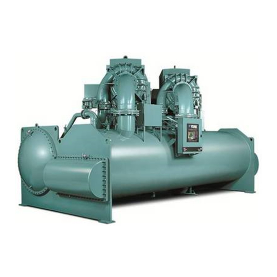
Page 7: Figure 1 - Front View Of Assembled Unit
All openings This instruction explains the procedure to be used for on the compressors and shells are closed and charged reassembling the Model YD Chiller shipped disassem- with dry nitrogen (5 to 7 PSIG). bled (Shipping Form 3 and 7). -
Page 8: Figure 2 - Form 7 Shipment
Refrigerant charge shipped in appro- opened and contents checked against the packing list. priate cylinders. Any material shortage should be reported to YORK When more than one chiller is involved, immediately (refer to Shipping Damage Claims (Form the major parts of each unit will be 50.15-NM)). - Page 9 FORM 160.69-NM4 ISSUE DATE: 9/30/2020 THIS PAGE INTENTIONALLY LEFT BLANK. JOHNSON CONTROLS...
-
Page 10: Table 1 - Dimensions - K Compressor Units Ft.-In.(Mm)
FORM 160.69-NM4 ISSUE DATE: 9/30/2020 TABLE 1 - DIMENSIONS – K COMPRESSOR UNITS FT.–IN.(MM) EVAPORATOR - CONDENSER SHELL CODES FT. - IN. (MM) DIMENSION 11'-6" 11'-6" 11'-11" 13'-4" 14'-6" 14'-6" 15'-0" 16'-0" (3,505) (3,505) (3,632) (4,064) (4,420) (4,420) (4,572) (4,877) 12'-8"... -
Page 11: Figure 3 - Dimensions - K Compressor Units Ft.-In. (Mm)
FORM 160.69-NM4 ISSUE DATE: 9/30/2020 UNIT DIMENSIONS Refer to Table 1 on page 10 for specific dimensions based on Evaporator-Condensor shell combinations. LOW VOLTAGE EVAPORATOR CONDENSER LD18374 FIGURE 3 - DIMENSIONS – K COMPRESSOR UNITS FT.–IN. (MM) JOHNSON CONTROLS... -
Page 12: Table 2 - Approximate Unit Weight Including Motor* - English (Metric)
FORM 160.69-NM4 ISSUE DATE: 9/30/2020 UNIT WEIGHTS TABLE 2 - APPROXIMATE UNIT WEIGHT INCLUDING MOTOR* — ENGLISH (METRIC) OPERATION WEIGHT EST. REFRIGERANT SHELLS COMPRESSOR SHIPPING WEIGHT (LBS/ KGS) ** (LBS/ KGS) CHARGE (LBS/ KGS) *** 74,800 (33,926) 92,500 (41,953) 6,000 (2,721) 83,200 (37,735) 104,100 (47,215) 7,300 (3,311) -
Page 13: Figure 4 - 150 # Design Evaporator, No Hot Gas Bypass
FORM 160.69-NM4 ISSUE DATE: 9/30/2020 TABLE 4 - EVAPORATOR SHELL WEIGHTS — 150# DESIGN, NO HOT GAS BYPASS SHELL CODE WEIGHT SHELL CODE WEIGHT 18600 40920 41500 91300 20100 44220 43200 95040 21600 47520 44800 98560 16800 36960 37600 82720 17800 39160 38700... -
Page 14: Table 5 - Condenser Shell Weights - 150# Design, No Hot Gas Bypass
FORM 160.69-NM4 ISSUE DATE: 9/30/2020 TABLE 5 - CONDENSER SHELL WEIGHTS — 150# DESIGN, NO HOT GAS BYPASS SHELL CODE WEIGHT SHELL CODE WEIGHT 18400 40480 35100 77220 19300 42460 27100 59620 23900 52580 28100 61820 15100 33220 28900 63580 16100 35420 30300... -
Page 15: Figure 5 - 150 # Design Condenser, No Hot Gas Bypass
FORM 160.69-NM4 ISSUE DATE: 9/30/2020 LD19865 FIGURE 5 - 150 # DESIGN CONDENSER, NO HOT GAS BYPASS JOHNSON CONTROLS... -
Page 16: Figure 6 - Rigging - Driveline Assembly
If utilizing any oil on the o-ring, it's recommended that you use LD19863a York "K" oil. See discharge line weight in Table 8 FIGURE 6 - RIGGING – DRIVELINE ASSEMBLY on page 18. -
Page 17: Table 7 - Approximate Unit Motor Weights - English (Metric)
FORM 160.69-NM4 ISSUE DATE: 9/30/2020 TABLE 7 - APPROXIMATE UNIT MOTOR WEIGHTS — ENGLISH (METRIC) LOW VOLTAGE WEIGHT WEIGHT WEIGHT WEIGHT 60 HZ 50 HZ LBS. LBS. 2,835 1,289 5,750 2,614 2,835 1,289 5,750 2,614 3,105 1,411 5,750 2,614 3,180 1,445 6,800 3,091... -
Page 18: Table 8 - Suction/Discharge Piping
FORM 160.69-NM4 ISSUE DATE: 9/30/2020 TABLE 7 - APPROXIMATE UNIT MOTOR WEIGHTS — ENGLISH (METRIC) (CONT'D) MEDIUM VOLTAGE MODEL MODEL WEIGHT WEIGHT WEIGHT WEIGHT (LBS.) (KGS.) (LBS.) (KGS.) 60 HZ 50 HZ 4,415 2,007 4,640 2,109 4,445 2,020 5,800 2,636 4,540 2,064 5,800... -
Page 19: Figure 7 - Oil Pump Housing
FORM 160.69-NM4 ISSUE DATE: 9/30/2020 6. Connect the oil drain lines between the com- 8. Tighten all hardware installed from the previous pressors oil drain flanges and oil pump housing steps 2 thru 8. flanges. Be sure to install the proper gaskets and 9. -
Page 20: Figure 11 - Re-Assembly
FORM 160.69-NM4 ISSUE DATE: 9/30/2020 LD09430 FIGURE 11 - RE-ASSEMBLY JOHNSON CONTROLS... -
Page 21: Figure 12 - Variable Speed Drive Bracket
FORM 160.69-NM4 ISSUE DATE: 9/30/2020 VSD Re-assembly 1. Install VSD bracket assembly. 2. Lift the Variable Speed Drive and remove all packing material, for Variable Speed Drive weight refer to Table 9 on page 21. Care- fully lower the Variable Speed Drive on to the supports on the condenser. -
Page 22: Figure 14 - Variable Speed Drive Rigging
FORM 160.69-NM4 ISSUE DATE: 9/30/2020 3. Re-connect motor power leads in the Variable Final Assembly Notes Speed Drive to T1, T2, and T3 terminals and 1. Pressure test. NOTE: Relief valves must be torque to 18-20 Ft-lbs. per the labels in the VSD. plugged (or capped) (refer to Operation (Form 160.69-O3)). -
Page 23: Table 10 - Si Metric Conversion
FORM 160.69-NM4 ISSUE DATE: 9/30/2020 The following factors can be used to convert from English to the most common SI Metric values. TABLE 10 - SI METRIC CONVERSION MEASUREMENT MULTIPLY ENGLISH UNIT BY FACTOR TO OBTAIN METRIC UNIT Capacity Tons Refrigerant Effect (ton) 3.516 Kilowatts (kW) Power... - Page 24 5000 Renaissance Drive, New Freedom, Pennsylvania USA 17349 1-800-524-1330 Subject to change without notice. Printed in USA Copyright © by Johnson Controls 2020 www.johnsoncontrols.com ALL RIGHTS RESERVED Form 160.69-NM4 (920) Issue Date: September, 2020 Supersedes: 160.69-NM4 (1215)
Need help?
Do you have a question about the YD and is the answer not in the manual?
Questions and answers