Table of Contents
Advertisement
Advertisement
Chapters
Table of Contents

Related Manuals for Siruba C007K


Summary of Contents for Siruba C007K
- Page 1 電控參數說明書 ELECTRONIC CONTROL PARAMETER MANUAL C007K/CHK...
- Page 2 EC - Manufacturer Declaration We declare herewith that the following equipment: NEEDLE POSITIONER AC SERVO MOTOR--- i SERIES . is designed to be a driver of a sewing unit or system and must not be put into commission until the sewing unit or system has been declared in conformity with the provision of the EC Machinery Directives.
- Page 3 有毒物質限量指令自我宣告書 Declaration of Conformity for Concentration Limits for Certain Hazardous Substances 本公司所生產之伺服馬達產品系列如下所列 : We declare herewith that the following AC servo motor series products list below : AC 伺服馬達--- i 系列/ G 系列/ GD 系列/ MD 系列 AC Servo Motor --- i Series / G Series / GD Series / MD Series Devrice---TK Series / TC Series / MK Series 皆符合以下指令及要求...
-
Page 4: Table Of Contents
型 式 : 系列 目 次 頁次 1.安全上的注意事項 1.1 作業環境的安全 ……………………………………………………………………………………… 1.2 安裝的安全 …………………………………………………………………………………………… 1.3 操作中的安全 ………………………………………………………………………………………… 1.4 保養維修的安全 ……………………………………………………………………………………… 1.5 保養維修的規定 ……………………………………………………………………………………… 1.6 危險標示、注意標示 ………………………………………………………………………………… 1.7 保固期限規定 ………………………………………………………………………………………… 2.安裝與調整 (1). 馬達的安裝 …………………………………………………………………………………………… (2). 控制箱的安裝 ………………………………………………………………………………………… (3). 控速器的安裝 ………………………………………………………………………………………… (4). 皮帶護蓋上的調整 …………………………………………………………………………………… (5). - Page 5 6.常用參數內容表 ……………………………………………………………………………………… 7.簡易故障排除 (1). 錯誤信息 ERO. 之顯示碼與排除對策 ………………………………………………………………… (2). 保險絲的更換 ………………………………………………………………………………………… 70M 部品表 ……………………………………………………………………………………… (3). 8.端子座 Pin 功能配置圖 70M - 7 -66 (V7) (07) …………………………………………………………………………………… (1). (2). 70M - 7 -46 (LT) (DW) (K1)………………………………………………………………………………… 70M - 7 –BR…………………………………………………………………………………………… 70M - 7 -7W ……………………………………………………………………………………………… 70M - 7 -11………………………………………………………………………………………………...
-
Page 6: 作業環境的安全
1.安全上的注意事項 : 使用前請詳細閱讀本技術資料與所搭配的縫製機械說明書,配合正確使用,並須 由接受過正確訓練的人員來安裝或操作。 在使用或安裝 i70M 型伺服馬達系列控制箱驅動裝置時,請注意下列事項。 本驅動裝置僅適用於指定範圍的縫製機械,請勿移做其他用途。 1.1 作業環境的安全 : (1).電源電壓 : 電源電壓請遵照控制箱銘牌所標示之規格 ±10 %範圍內操作。 (2).電磁波干擾 : 擾本驅動裝置因而發生 請遠離高週磁波機器或電波發射器等,以免所產生的電磁波干 錯誤動作。 雜訊干擾 請遠離雜訊干擾 (3).溫濕度 : a.請不要在室溫 45°C 以上或 5°C 以下的場所操作。 b.請不要在日光直接照射的場所或室外運作。 c.請不要在暖氣 (電熱器) 旁運作。 d.請不要在相對濕度 30 % 以下或 95 % 以上或有露水的場所運作。 (4).空氣... -
Page 7: 操作中的安全
棕色線 如用於單相 220 V 三相接線 黑色線 (AC220V) 時此(黑色線)不接。 藍色線 OFF ON 綠 / 黃線 ( 接地線 ) 接控制箱 b.電源線的接地線須以適當大小的導線和接頭連接到生產工廠的系統地線,此連接必須 被永久固定。 接地線 (綠/黃 色) 請務必做好接地工程。 如果沒有接地,漏電流將對人體造成不適或傷害。 1.3 操作中的安全 : (1).在第一次開電後,請先以低速操作縫紉機並檢查轉動方向是否正確。 (2).縫紉機運轉時,請不要去觸摸皮帶輪、三角皮帶、天枰、針等會作動的部位。 (3).所有可作動的部份,必須以所提供的防護裝置加以隔離,防止身體接觸並請勿在裝置內塞 入其他物品。 (4).請不要在拆下皮帶護蓋及其他安全裝置的情形下操作。 1.4 保養維修的安全 : 在操作以下動作前,請先關閉電源 : (1).要拆卸馬達或控制箱時,或在控制箱上插或拔任何連接插頭時。 (2).控制箱裡面有危險高壓電,所以關閉電源後要等 10 分鐘以上方可打開控制箱蓋。 頭... -
Page 8: 安裝與調整 (1). 馬達的安裝
2. 安 裝 與 調 整 (1).馬達的安裝 : A). M1 直驅型: (馬達與車頭結合或懸掛在一起的安裝方式) 請參閱各車頭製造廠之說明書。 B). M1 泛用型: (馬達鎖裝在車板下的安裝方式) 請參照下列『車板鑽孔尺寸圖』 ,將馬達懸掛安裝。 一般標準尺寸圖 (USA 標準) 電纜線穿過孔尺寸圖 德國標準 DIN 尺寸圖 鉆 9 mm 孔 鉆 9 mm 孔 鉆 40 mm 孔 車 板 車... - Page 9 三本車模式-定位調整 1.請先取下散熱風葉。 2.轉動心軸使天枰停在最高點位置 (或車頭指定之上停針位置點)。 螺絲(B) 3.轉動反光片座使螺絲(A)對準馬達 磁石座 出口線位置。 註:上述調整為標準調法,如覺得 散熱風葉 定位不準,可自行進行微調。 出口線 螺絲(A) 拷克車的模式-馬達的安裝 1.將車頭的散熱風扇及皮帶輪卸下。 ○ ○ A 放入車頭心軸內,散熱風扇端靠緊心軸端面。並使用心軸墊環 B 將聯軸器確實固定於車 2.將附件的聯軸器 頭心軸。注意:車頭心軸端面若無預留螺絲孔則不組裝心軸墊環。 ○ ○ 3.固定聯軸器的 set 螺絲 C 。注意:聯軸器特殊爪型的 set 螺絲固定於心軸平面或凹槽上 D 。 4.將 M5 馬達 E 固定於車頭端面上。 注意:車頭端聯軸器與馬達端聯軸器有防呆設計,組裝時需注意配合方向。 ○...
-
Page 10: 控制箱的安裝
拷克車的模式-定位調整 1. 請先取下車頭手輪。 2. 轉動心軸使天枰停在最高點位置 (或車頭指定之上停針位置點)。 3. 轉動反光片座使螺絲(A)對準馬達出口線位置。 註:上述調整為標準調法, 如覺得定位不準, 可自行進行微調。 (2).控制箱的安裝 : a).車板右側面須預留 100 mm 以上空間 70M 控制箱鎖裝於車板下方 b).將 c).安裝後示意圖 尺寸圖 239mm 231.4mm 控 制 100 mm 箱 預 留 空 間 171mm 60mm (3).控速器的安裝 : a).控速器與其支架座 b).保持在吊桿成直線下,將控速器連座鎖於車板下方 c).安裝後示意圖 控速器支架... -
Page 11: 定位器(傳感器)的安裝與調整
B.皮帶止落檔片的安裝調整 : a. 出廠時『皮帶止落檔片』均預’裝於適用皮帶輪直徑 100 mm 以上的位置 (如圖示 A ),如須變更皮帶輪時,請參照如下圖示。 b. 調整皮帶止落檔片方式 : 已知皮帶輪尺寸請按皮帶蓋表面刻度調整固定。若不知皮帶輪尺寸,請由外往內推至頂到皮帶輪後,再 返回 5~10mm 左右。 從護蓋外面 看 皮帶輪直徑 100 mm 以上 皮帶輪直徑 90 mm 以下 的鎖裝方式 (如圖示 A ) 的鎖裝方式 (如圖示 B ) 皮帶止落檔片鎖裝方式 ( 如 右 圖 示 ) (5).皮帶護蓋的安裝調整... - Page 12 『針上』位置設定 : 用手轉動車頭皮帶輪,使天枰停在最高點位置(或車頭指定之上停針位置點),再將 上定位感應片(A) 的紅點對準底座的基準紅點。 『針下』位置設定 : 用手轉動車頭皮帶輪,使針停在最低點位置(或車頭指定之下停針位置點) ,再將 下定位感應片(B) 的藍點對準底座的基準紅點。 註 : 上述調整說明為標準調法,如覺得定位不準,可自行進行微調。 輕 重 (7).控速器前、後踏力量的調整 : 控速器各部位名稱 : 如右圖示 A : 前踏力量彈簧。 B : 後踏力量的調整螺栓。 C : 踏板旋臂。 D : 腳踏板吊桿。 輕 重 調 整 結 果 調整需求 當彈簧...
-
Page 13: 接線與接地 (1). 單相與三相電源線的接法
3. 接 線 與 接 地 : (1).單相與三相電源線的接法 : 綠/黃色電線為接地線,一定要做好系統的接地工程,請洽合格的電氣工程人員予以施工。 棕色線 單 相 接 線 PVC 電源線 藍色線 綠 / 黃 色線 棕 如用於單相 220 V 黑 時此(黑色線)不接。 三 相 接 線 藍 接至控制箱 綠 / 黃 ( 接地線 ) 1. - Page 14 (4).當單相 220 V 伺服馬達欲使用在三相 220V 的電壓時 , 須注意配置使用上的負載平衡 : 連接相當多數量縫紉機配置使用時,需考慮三相中 R、S、T 各相的平衡,如下圖示 : (5).如何變換電磁閥 (Solenoid) 的供應電壓 : ( DC 24 V 或 30 V ) 當電磁閥線圈 (Solenoid) 的使用電壓,如欲由 24 V 改成 30 V 或 30 V 改成 24 V 時,其主基板組的 JP1 與...
-
Page 15: 控制箱正面
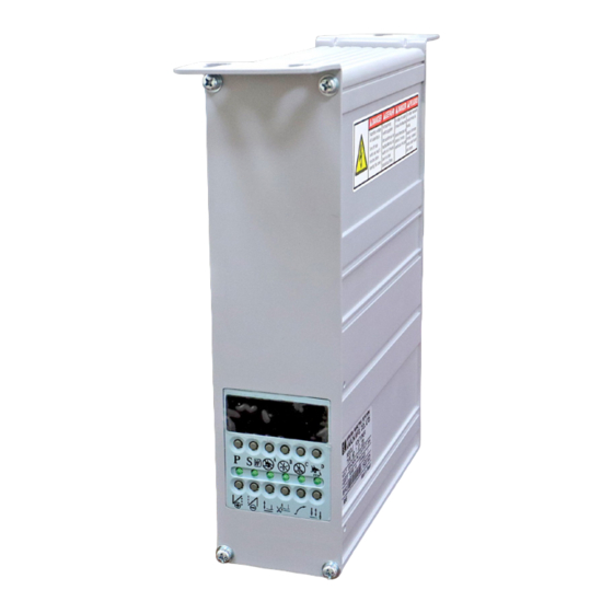
4.控制箱各部位的名稱 : (1).控制箱正面 : 顯示器螢幕 針數設定 / 特殊功能 選擇 在平車時為針數選擇 在三本車為特殊功能 參數呼叫 功能鍵 STOP 參數儲存 功能鍵 針停 上 / 下 設定鍵 起始回縫 功能鍵 慢速起縫 設定鍵 終止回縫 功能鍵 切線後 自動抬押腳 中立時 自動抬押腳 (2).控制箱背面 : 端子座面板 (範例 : 70M-7-66) AC POWER IN 馬達電源插座... -
Page 16: Led 字幕畫面的顯示模式
5.LED 字幕畫面的顯示模式 : (1).在【一般模式】畫面區,三本車機型時面板按鍵的功能與定義 : 取消『 半後踏功能 』鍵 無 作 用 : 表示已無半後功能 取消『 切線功能 』鍵 進入參數區功能鍵 : 表示已無切線功能 取消『 掃線功能 』鍵 馬達旋轉符號 : 表示已無掃線功能 起始定針縫功能鍵 : 表示開啟 (燈會亮) 無 作 用 特殊功能設定狀態顯示 STO P 馬達停止時針停設定鍵 針上 / 針下 車縫途中停止時自動 抬押腳... -
Page 17: 如何進入第二階【參數模式 B 】畫面區的操作步驟
(3).如何進入第二階【參數模式 B】畫面區的操作步驟 : ( B 區可選參數範圍為 : 1 ~ 122 ) 鍵,同時開啟電源開關,即進入【參數模式 B 】畫面區中的第 b.以手按住 a.如在操作中,請先關閉電源開關 一個畫面【 047.MAC 】 。 STO P STOP e. 進入內容區後再以相對應之 註 1. 最後按下 鍵後,即自動回 再以 或 鍵找出欲設定的 等鍵調整所須之內容值。 至【一般模式】的操作畫面。 參數序號,如範例 :【 048. N12 】 f. 調整後須按下 鍵予以儲存確認。... - Page 18 (4).在【參數模式 A 與 B 】畫面區時,面板按鍵的功能與定義 : ( 如下範例圖示 ) 七段顯示器參數畫面 進入『 內容區 』功能鍵 同『遞增參數』選擇鍵 在此模式下,無作用 STOP 『 遞增參數 』選擇鍵 在此模式下,無作用 『 遞減參數 』選擇鍵 進入第一階【參數模式 A 】畫面區時,第一個出現畫面為【 001. H 】 ,其參數可調範圍為 1 ~ 46 項。 七段顯示器 進入第二階【參數模式 B 】畫面區時,第一個出現畫面為【 047. MAC 】 ,其參數可調範圍為 1 ~ 122 項。 畫面模式...
- Page 19 B).將內容值或數值,調整比原預設值『 還低 』時的調整方式 : 例如 : 將出廠預設值【H. 4500】調低為 4000 轉時 : 請依第 5 章節的 ( 4 ) 或 ( 5) 敘述之 a、b、c 進至『內容區』畫面後,再依如下步驟逐步進行其數值調整設定。 d. 進入至內容區,如【H.4500】 e. 連按 鍵,一直遞增數值回歸至 0 STOP STOP h. 回到【一般模式】操作區畫面 f. 調整至欲設定數值 4000 後 鍵予以儲存確認 g.按 STOP STOP STOP (6).在『參數內容區』時,A、B、C、D 鍵調整設定的表示值...
-
Page 20: 常用參數內容表
6.常用參數內容表 : 階級 參數代碼 內 容 說 明 範 圍 內 容 值 名 稱 說 明 與 備 註 最高轉速 ( spm ) 50 ~ 9999 車縫時的最高運轉速度調整。 001. H 參 起始回縫速度 ( spm ) 50 ~ 8000 起始回縫 ( 或三本車機型的定針縫 ) 的速度調整。 004. -
Page 21: 錯誤信息 Ero. 之顯示碼與排除對策
7.簡易故障排除 : (1).錯誤信息 ERO. 之顯示碼與排除對策 : 信 息 碼 內 容 狀 態 與 對 策 馬達與車頭出力將全部關閉成無動作狀態。 請檢查供應此控制箱之 AC 電源是否正確。 ( 或是否超過使用規定的額定電壓 ) 1. 電源 ON 時,主電壓檢知過高時。 *如控制箱為 AC 220V 系統, 請勿使用 AC 380V 的電源,否則 LED 於送電 2 秒 ER0. 4 2. -
Page 22: 保險絲的更換
(2).保險絲的更換 : 保險絲位置與規格 : 如保險絲燒斷時,請先把原因排除後再更換相同容量的保險絲。 基板組正視圖 : F1、F2 保險絲為 15 A / 250V ( AC 電源入力保護用 ) 注 意 : 在打開控制箱蓋之前,請先將電源關閉約 10 分鐘後,才可打開控制箱蓋。... -
Page 23: I 70M 部品表
70M 部品表: 控制箱部份 馬達部份 配件部份 編號 元件料號 品 名 規格與備註 編號 元件料號 品 名 規格與備註 馬達本體組 依客戶選用 端子座 2VP34XX209XXX 32ZVPBC80 馬達腳座組 下掛式馬達專用 圓頭螺絲 1-1 2VPBTV020 2-10 331SP1150 皮帶蓋上蓋 下掛式馬達專用 透明視窗 1- 2 315BGV080 2-11 315MPB840 皮帶輪 依客戶選用 操作面板 黃色系 1- 3 2VP2PY40XXX 2-12 315MPBA8B 皮帶蓋底座... -
Page 24: 端子座 Pin 功能配置圖
8. 端子座 Pin 功能配置圖 : (1). 70M-7-66:(V7) (07) -
Page 25: I 70M-7-46:(Lt) (Dw) (K1)
(2). 70M-7-46:(LT) (DW) (K1) - Page 26 (3).i70M-7-BR:...
- Page 27 (4). i70M-7- 7W:...
- Page 28 (5). i70M -7-11:...
- Page 29 (6). i70M -7-98: 其他功能出力...
- Page 30 (7). i70M -7-70:...
- Page 31 Model : M Series Contents 1. Safety Precaution Page 1.1 Work environment ……………………………………………………………………………………… 1.2 Safety in installation …………………………………………………………………………………… 1.3 Safety in operating …………………………………………………………………………………… 1.4 Safety in maintenance and repairs …………………………………………………………………… 1.5 Regulation in maintenance and repairs ………………………………………………………………… 1.6 Danger and caution signs ……………………………………………………………………………… 1.7 Warranty information ………………………………………………………………………………...
- Page 32 Page 6. General Parameter Table ……………………………………………………………………… 7. Basic Troubleshooting (1). Error code and measurement …………………………………………………………………………… (2). Instruction of fuse replacement ………………………………………………………………………… (3). 70M parts list ………………………………………………………………………………………… 9. Basic Diagrams of Connector Panel (1). 70M-7-66 (V7) (07)………………………………………………………………………………………… (2). 70M-7-46 (LT) (DW) (K1)………………………………………………………………………………… 70M-7-BR……………………………………………………………………………………………...
-
Page 33: Safety Precaution
1. Safety Precaution: Please read this manual carefully, also with related manual for the machine head before use. For perfect operation and safety, installing and operating this product by trained personnel is required. When install and operate 70M Servo Motor, precaution must be taken as the following. This product is designed for specify sewing machines and must not be used for other purposes. -
Page 34: Safety In Operating
(4). Grounding: a. To avoid the static interference and current leakage, all grounding must be done. b. Use the correct connector and extension wire when connecting ground wire to Earth and secure it tightly. Single phase ( AC110V / 220V ) Brown wire Ground Wire (Green/Yellow) -
Page 35: Installation And Adjustment (1). Motor Installation
2. Installation and Adjustment: (1). Motor installation: A). When motor and machine installed together, refer to the machine head’s instruction. B). When motor installed under the working table, drill holes in the table as the following diagram for the installation. For USA Base For Cable For Din Base... - Page 36 Adjust on needle position 1. First step: takes off the exhaust fan of motor. 2. Turn the shaft gets the scale to stop at highest point (or the up position point in sewing machine). Screw (B) Retlector Slice base 3. Turn the encoder disc to screw (A) to aim at the wire outlet of motor.
-
Page 37: Control Box Installation
Adjust on needle position 1. Takes off hand wheel of sewing machine. 2. Turns the shaft gets the scale stop at highest point (or the point of up position in sewing machine). 3. Turn the encoder disc and the screw (A) to aim at wire outlet of motor. -
Page 38: Install The Belt Cover
B. Belt Stopper Adjustment: a. Factory default Belt stopper is mount at pulley scale about 100 mm’s position (Fig. A ), if pulley size change, follow the Fig. B. b. Adjustment tips: Move stopper pointer aligned with any position at pulley diameter scale that matches the pulley diameter size, if didn’t know the pulley diameter size, please push the stopper until to touch the pulley then return back 5-10mm position. -
Page 39: Adjust The Speed Control Unit
Needle up position : Rotate the machine pulley to reach mechanical needle up position and turn the photo plate (A) until its red mark is aligned with the red mark on the bearing cover plate. Needle down position : Rotate the machine pulley to reach mechanical needle down position and turn the photo plate (B) until its blue mark is aligned with the red mark on the bearing cover plate. -
Page 40: Power Connection And Grounding (1). Single Phase And Three Phase Connection
3. Power Connection and Grounding: (1). Single phase and three phase connection: Green/yellow wire is the ground wire. Brown wire Single Phase PVC Cable Blue wire Green/Yellow wire Brown If use on single phase Black Three Phase (220 V), don’t connect the black wire. -
Page 41: The Load Balance When Use A 1Φ / 220 V Motor Used On A 3 Φ / 220 V Power Source
(4). The load balance when use a 1Φ / 220 V motor used on a 3 Φ / 220 V power source. See the following figure for the load balance. (5). How to change solenoid supply voltage (DC: 24 V OR 30 V) :... -
Page 42: Diagrams Of Control Box
4. Diagrams Of Control Box: (1). Front side: 7-segment LCD Setting number of stitches for Lockstitch machine. Special function setting for Interlock stitch.machine STOP Callout Parameter Needle UP/Down Save Parameter Slow Start ON/OFF Presser foot UP after Start Tacking ON/OFF trimming End Tacking ON/OFF Presser foot UP when... -
Page 43: Programmable 7-Segment Display
5. Programmable 7-segment Display (1).Key functions in the【Normal Mode】on a interlock stitch machine Cancel Half Heeling No Function : No Half Heeling Function Cancel Trimmer Enter Value area : No Trimmer Function Motor rotation Cancel Wiper Direction icon : No Wiper Function Start Constant Stitch Sewing : On (LED will light ) No function... -
Page 44: How To Access 【Parameter Mode B
(3). How to access 【Parameter Mode B】 : (Available parameter codes:1~122 ) b. Press hold □ key and turn on the power to access the first parameter a. Turn off the power code 【047.MAC】of【parameter mode B】 STOP STO P Note 1.After pressing □ key, it will c. - Page 45 (4).Key functions in the Parameter【Mode A and B】 :(Example as the following) 7-segment Enter Value area display Same as parameter increment key STOP No function Parameter No function increment key Parameter decrement key In 【Mode A】 First parameter showing is 【001. H】 All available parameter start 1~46. 7-segment display In 【Mode B】...
- Page 46 B). How to decrease the default value: Example:Factory default setting【H. 4500】decrease to【H. 4000】 : (See chapter 5, section (4) or (5) to learn how to access a、b value setting, then do the following step by step ) d. Into 【H.4500】value area e.
-
Page 47: General Parameter Table
6. General Parameter Table : Parameter Range / Mode Parameter Function Description / Note Code Selection 50 ~ 9999 001. H Maximum sewing speed ( spm ) Maximum speed adjustments. Start Back-Tacking speed or Speed adjustment for Start Back-Tacking or Constant-Stitch 50 ~... -
Page 48: Basic Troubleshooting (1). Error Code And Measurement
7. Basic Troubleshooting : (1). Error Code and Measurement: Error Code Cause of The Problem Status and Measurement Motor and machine will be shutting down. Please check the AC power. (Too high) *If control box is AC 220V system, don’t use the AC 380V power voltage, 1. -
Page 49: Instruction Of Fuse Replacement
(2). Instruction of Fuse Replacement Fuse Type and Location:When fuse fused, find out the cause and fix it before replace the new one Main Board Top View F1 / F2 Fuse is 15 A / 250V ( For AC Power Protection ) Caution:... -
Page 50: I 70M Parts List
70M Parts List: Control Box Assembly Motor Set Assembly Accessories Order Code Parts Name Description Order Code Parts Name Description 2VP34XX209XXX Motor Set Option 32ZVPBC80 Terminal board 1-1 2VPBTV020 Motor Base For V-Belt Type 2-10 331SP1150 Screw Transparent 1- 2 315BGV080 Belt Cover Top For V-Belt Type 2-11 315MPB840 window... -
Page 51: I 70M-7-66 (V7)
8. CONNECTOR DIAGRAM: (1). 70M-7-66:(V7) (07) -
Page 52: I 70M-7-46 (Lt) (Dw) (K1)
(2). 70M-7-46:(LT) (DW) (K1) -
Page 53: I70M-7-Br
(3).i70M-7-BR:... - Page 54 (4). i70M-7- 7W:...
- Page 55 (5). i70M -7-11:...
- Page 56 (6). i70M -7-98: 其他功能出力...
- Page 57 (7). i70M -7-70:...
- Page 58 七段顯示器字體與實際數值對照表 : 7-Segment Display Characters Compare Table 數值字體部份 : (Arabic Numerals) 實際數值 Actual 七段顯示器 Display 英文字體部份 : (English Alphabet) 英文數字 (Actual) 七段顯示器 (Display) 英文數字 (Actual) 七段顯示器 (Display) 英文數字 (Actual) 七段顯示器 (Display) 版權所有.仿冒必究 Violators will be prosecuted...
- Page 59 由於對產品的改良及更新 , 本產品使用說明書中與零件圖之產品及外觀的修改恕不事先通知 ! The specification and/or the equipment described in the instruction book and parts list are subject to change because of modification with out previous notice APR.2021...