
Related Manuals for Godex ZX1000i Series


Summary of Contents for Godex ZX1000i Series
- Page 1 ZX1000i Series ZX1000Xi Series THERMAL LABEL PRINTER USER MANUAL User Manual: ZX1000i Series Version : 2.3 Issue Date : 2021/11/24 : 920-015111-00...
-
Page 2: Table Of Contents
目錄 1 Barcode Printer ..............................................5 1.1 Box content ............................................5 1.2 Getting to Know Your Printer......................................6 2 Printer Setup ................................................8 2.1 Loading the label roll .......................................... 8 2.2 Loading & Removing the Ribbon ....................................12 2.3 Connecting the Printer to the Host Computer ................................14 2.4 Installing Printer Driver and GoLabel with Super Wizard CD ............................15 3 Printer Setting and Control ..........................................20 3.1 Operation Panel ..........................................20... - Page 3 ZX1200i/ZX1200Xi Series FCC COMPLIANCE STATEMENT FOR AMERICAN USERS Federal Communication Commission Interference Statement This equipment has been tested and found to comply with the limits for a Class B digital device, pursuant to Part 15 of the FCC Rules. These limits are designed to provide reasonable protection against harmful interference in a residential installation.
- Page 4 SAFETY INSTRUCTIONS Please read the following instructions carefully. 1. Keep the equipment away from humidity. 2. Before you connect the equipment to the power outlet, please check the voltage of the power source. 3. Make sure the printer is off before plugging the power connector into the power jack. 4.
-
Page 5: Barcode Printer
1 Barcode Printer 1.1 Box content Please check that all of the following items are included with your printer. (Package content and Logo style may vary per region.) • Barcode Printer • Label Stock • USB Cable • Quick Guide •Ribbon •Power Cord... -
Page 6: Getting To Know Your Printer
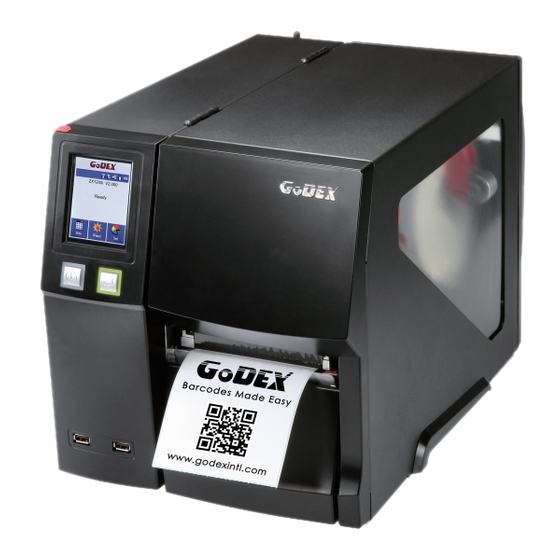
1.2 Getting to Know Your Printer Device Overview •Front View Stylus pen Printer cover Touch panel Viewing window Power button Feed button Lower cover plate USB Host •Rear View Feed slot for continuous labels Calibration button Ethernet port Serial port (DB-9) Applicator Interface(OPTION) USB port USB Host... - Page 7 •The Internal View of Printer Ribbon rewind hub Ribbon supply hub Print mechanism Platen roller Release lever for print head Paper guide Label tension guide Label roll guide Label supply hub Adjustable Sensor Paper guide...
-
Page 8: Printer Setup
2 Printer Setup 2.1 Loading the label roll This printer supports the following printing methods: Thermal transfer printing (TTP):Requires a ribbon for transferring a printed image to a medium. Direct thermal printing (DTP):Does not require a ribbon, only thermal paper. Please check which printing method you are using and alter the settings accordingly in the printer driver, printer menu, and/or software. - Page 9 Now slide the label roll guide forward and fold it down Place the label roll on the label supply hub, pushing it right up to the printer housing. (Do not apply too much pressure to avoid damaging the label stock.) Note ————————————————————————————————————————...
- Page 10 Load the label roll into the printer as shown in the illustration. Pass it through the printer as indicated by the red arrows. Pass the label stock through the Adjustable Sensor and up to the tear-off plate. Note —————————————————————————————————————— * Remember to set the movable sensor to gap, black mark, or tag hole by changing the position of the sensor with the adjustment wheel.
- Page 11 2. Return the print head release lever to its original position. 1. The labels pass between the wall of the printer housing and the adjustable paper guide. Then close the printer cover.
-
Page 12: Loading & Removing The Ribbon
2.2 Loading & Removing the Ribbon Loading Ribbon Place the printer on a flat surface and open the printer cover Place a new ribbon on the ribbon supply hub. The two illustrations as below show you how to install the ribbon depending on the ribbon type (ink side in or out). Ink side out Ink side out... - Page 13 Pass the ribbon under the print head and back up on the other side. Attach it to the empty ribbon core. Note —————————————————————————————————————— * Do not pass the ribbon under the sensor.
-
Page 14: Connecting The Printer To The Host Computer
2.3 Connecting the Printer to the Host Computer 1. Please make sure that the printer is switched off. 2. Connect the power cord to the AC adapter and connect the adapter to the printer. 3. Connect the USB cable to the printer and host computer. 4. -
Page 15: Installing Printer Driver And Golabel With Super Wizard Cd
The wizard will then ask you to make sure your USB and power cables are connected and that the power is turned on. Make sure that is done and then click “Next”. The next screen you will see to choose “Download the latest version from GoDEX server” or “Install from this product disc.”... - Page 16 As the printer driver and GoLabel are installing, a screen will display a progress bar. Once the installation is complete, you can start to make and print labels with GoLabel or through the printer driver. As the optional steps, you can also print a test label or register your printer during the “Standard Installation”procedure. Note ——————————————————————————————————————...
- Page 17 Installing Printer Driver Directly from CD Folder Insert the product CD in the CD/DVD drive of the host computer and open the "Seagull Drivers" folder on the CD. Select the icon for the driver file and click it to start the installation. Follow the instructions on the screen.
- Page 18 Specify the port used to connect the printer to the host computer. Enter a printer name and assign the appropriate rights. Once the installation is complete, a summary of the printer settings is displayed. Check whether the printer settings are correct and click "Finish" to start copying the driver files. Wait until copying is complete, then finish the installation.
- Page 19 Once the driver installation is complete, the new printer should appear in the "Printers and Faxes" folder.
-
Page 20: Printer Setting And Control
3 Printer Setting and Control 3.1 Operation Panel OPERATION TOUCH PANEL TOUCH PANEL FEED BUTTON POWER BUTTON POWER Button Press the POWER button to turn on the printer, and the START UP SCREEN appears. The printer is on “ready to print” status, the LCD screen should display the message “READY“... -
Page 21: Lcd Interface Introduction
3.2 LCD Interface Introduction Getting Started Press the POWER button to turn on the printer, and the START UP SCREEN appears. Power on If the printer is on “ready to print” status, the LCD screen should display the message “Ready” on the screen. Use touch gestures to get around the Home screen and other screen for setting. - Page 22 On the Ready Page, three function mode for setting. You can make various setting functions in FUNCTIONAL MODE. Tap “Main” -- Screen could show more detail of “Main” Tap “Wizard “-- Set up printer of “Darkness” “Speed” ... Tap “Test”-- self-Test page and Out of Dump Mode for setting.
- Page 23 finish setting tap back to main page if do not save, tap system would not save any changes. UNLOCK LOCK If printer functions locked, printer can not receive any commands from GoLabel or any devices.
- Page 24 Keyboard Mode When plug-in an USB keyboard to the printer, LCD touch panel will display “Enter Standalone”, press the “Y” key on keyboard to entering to the dialog for “Keyboard Mode” operation. Preview Label function User can choose any labels which have done in the printer and preview it. (See Instuctions) From the Home screen, tap to Main Page.
- Page 25 From the Recall Label page, the touch panel shown on all labels. The Data processing time will be extended as long as the labels increase. Tap up to choose labels. Tap down to choose labels. Tap Preview Label can see printing label Keeping tap to next page Print out selected label.
-
Page 26: Lcd Interface Function
3.3 LCD Interface Function Main Page Setting items for printer, ex. Printing speed, darkness.Also includes a Printing Wizard for your ease of printing. More than 10 languages for printer setting It consists of a table of values that describes the character set for a particular language Setting items for printing label, ex. - Page 27 Device Page Setting off or on for buzzer Setting items for options, ex. Cutter, Label Dispenser, Applicator Setting Programing Language. Auto/EZPL/GEPL/GZPL/GDPL Setting items for Serial Port, ex. Baud Rate, Parity, Data Bits, Stop Bits. Setting items for LAN, ex. Port NO., DHCP, Dynamic IP, Default Gateway, Subnet Mask. Setting items for LCD, ex.
- Page 28 Setting Items in Setting Mode Darkness 0-19 Speed Auto Select Media Detection See-Through Reflective Sensor Select Label with Gaps Printer Setting Media Type Label with Marks Continuous Direct Thermal Printing Mode Thermat Transfer Tear-off Position 0-40 Apply Top of Form Cancel English Deutsch...
- Page 29 Win 1254 Win 1255 Win 1257 Rotation X-offset Label Setting Y-offset Start Offset...
- Page 30 Buzzer None Cutter Optional Setting Label Dispenser Applicator Programing Language Auto/EZPL/GEPL/GZPL/GDPL 4800 bps 9600 bps 19200 bps Baud Rate 38400 bps 57600 bps 115200 bps Serial Port Setting Parity Even Device 7 bits Data bits 8 bits 1 bits Stop bits 2 bits DHCP IP Address...
- Page 31 Label with Marks Continuous X-Offset Y-Offset Enable Clear Bind Disable Enable Make Device Visible Disable Bluetooth Enable Disable PIN Code 0000 Search Devices...
- Page 32 Status of LCD Interface When printer is on standby status (ready to print), the LCD interface will display “Ready” on screen. You can only print when you see the “Ready“ status. If there is any printers error, the LCD screen will display the error screen to show the type of error. You can fix the error according the notice.
-
Page 33: Label Calibration And Self Test
3.4 Label Calibration and Self Test Label Calibration The printer can automatically detect and store label height. That means the host computer does not need to transmit the label height to the printer. Self Test Self-test function lets you check whether the printer is functioning normally. Here is how you run the label size calibration and self test. - Page 34 Label Calibration Button A hardware button to make a Label Calibration while printer encountering “Media Error” during the cases when first-time printer start up or change label or ribbon to another type, such as change using gap label to continuous or black mark labels. CALIBRATION BUTTON Press Press C-button for 2 seconds, it will make an auto-sensing to calibrate the label and ribbon’s parameters.
-
Page 35: Error Alerts
3.5 Error Alerts In the event of a problem that prevents normal functioning of the printer, you will see an error message on LCD screen and hear some beep signals. Please refer to below table for the error alerts. OPERATION LCD TOUCH PANEL TOUCH PANEL FEED BUTTON... - Page 36 run the autodetection function again. Replace the label Paper is finished. roll. Possible reasons: the print medium has become trapped around the rubber roll; the sensor cannot Printer feed problem. detect a gap or black mark between the labels; there is no paper.
-
Page 37: Usb Host
USB memory stick : It supports hot-plugging function; printer will create a Folder “\LABELDIR” and switch “User Flash” to “Extended Memory” automatically while user plugs an USB memory stick into a GoDEX printer. Connect the USB Stick plugged -in printer to PC via USB Device or Ethernet port and run “GoLabel” software to download Graphic, ... - Page 38 “Keyboard Mode”. Note ─────────────────────────────────────────────────────────────────────────────────────── The USB Host port on GoDEX printer is without “HUB” function. The USB Memory Stick supports with “FAT32” Disk Format and up to 32GB only. The certified venders are Transcend, Apacer, Patriot, Consair and Kingston. The download function for Graphic, Font, Label Format, DBF and Command files is operated by GoLabel of PC and must go through the a “i”...
-
Page 39: Netsetting For Ethernet
4 NetSetting for Ethernet 4.1 Installing the NetSetting software The NetSetting software is used to manage the network configurations when connecting the printer via Ethernet port. It is available on product CD or can be downloaded from official website. To install the NetSetting, please follow below steps. 1. -
Page 40: The Interface Of Netsetting
Click the NetSetting icon to start the program; you will see the start page as below. The start page will display the basic information of connected printer and your PC. Click the magnifier icon to search the Godex printers which are connected via Ethernet port in you network environment. Once a connected Godex printer is detected, it will be listed on the start page. - Page 41 IP Setting The IP Setting tab can change the printer name, Port number, Gateway setting and the password for configuring the printer. You can also set the printer’s IP address ether by DHCP or by Static IP. You can press “Set” button to apply the settings and “ReGet” button to refresh the setting values. Notice To fully benefit from the NetSetting software, you should be familiar with basic networking principles.
- Page 42 Alert Path Setting NetSetting will send the alert messages to designated mail account when the error happened on printer. The alert messages are sent by SMTP (Simple Mail Transfer Protocol) or SNMP (Simple Network Management Protocol). You can set or change the configurations of SMTP and SNMP on this “Alert Path Setting” tab. You can press “Set”...
- Page 43 Alert Message Setting For the alert message notification function, you can decide which error cases need to be sent out to the operator. Moreover, the alert messages can be set to be sent by SMTP, SNMP or both. You can press “Set” button to apply the settings and “ReGet” button to refresh the setting values.
- Page 44 Printer Configuration Set or change the configurations of connected printer. Most of key settings for the printer operation can be done by this setting page. You can press “Set” button to apply the settings and “ReGet” button to refresh the setting values.
- Page 45 User Command The “User Command” tab provides a communication interface for operator to control the printer. Input printer commands in "Input Command" window and press “Send Command” button, the commands will be sent to the printer. For some commands that will return response message, the message will be displayed in "Output Message" window. You can press “Send Command”...
- Page 46 Firmware Download On “Firmware Download” tab, the current version of printer firmware will be showed on the screen. If you need to update the printer firmware, just specify the file location of firmware file and press “Start Download Firmware” button. The printer firmware then can be updated remotely.
-
Page 47: Preparation Steps
5 Preparation Steps 5.1 Preparation Steps Before installing the optional modules, please make some preparations as follows. Turn off the printer : Remember to switch off the printer before installing any module Open the printer cover Place the printer on a flat surface and open the printer cover Notice... -
Page 48: Installing The Cutter
5.2 Installing the Cutter The Overview of the Cutter 1. Cutter module 2. Screw Unscrew the screw marked in the illustration on the front of the printer, which secures the lower cover plate. Remove lower cover plate to the a little bit right then can get out. - Page 49 Connect the cutter cable connector to the cutter jack on the printer. Be sure the cutter module insert to printer properly. (see red arrow)
- Page 50 Secure the cutter module on the printer housing using the screws. Finish the cutter module installed. Now load the label roll into the printer and close the printer cover. Notice **Check whether the cutter function is enabled in the printer. * Labels or paper should be at least 30 mm high.
-
Page 51: Maintenance And Adjustment
6 Maintenance and Adjustment 6.1 Installing / removing the print head module Open the printer cover. using a screwdriver or a coin, loosen the screw to take out the TPH module. Turn the print head counterclockwise to a top right position Hold the print head module, pull out the TPH cable smoothly. -
Page 52: Adjusting The Print Line
6.2 Adjusting the print line Open the printer cover. using a screwdriver or a coin to loosen the screw Turn the print head counterclockwise to a top right position If no improvement is visible, turn the screws(A) indicator board clockwise or counterclockwise as far as possible and be sure to align with the indicator board and indicator line. -
Page 53: Adjusting Ribbon Tension
6.3 Adjusting ribbon tension You can adjust the ribbon tension by turning the ribbon shaft knob (see illustration) clockwise or counterclockwise. There are 4 possible settings, which is marked on the ribbon supply hub. # 1 : Tension is the highest # 4 : Tension is the lowest If the tension is so low that the ribbon does not move forward, you need to reduce the tension of the ribbon supply hub. -
Page 54: Cleaning The Thermal Print Head
6.4 Cleaning the thermal print head Dirt on the print head or ribbon may result in inadequate print quality (there are only partial images on the label). The printer cover should therefore be kept closed when possible. Keeping dirt and dust away from the paper or labels ensures a good print quality and a longer lifespan of the print head. Here is how you clean the print head: 1. -
Page 55: Adjusting The Balance And Print Head Tension
6.5 Adjusting the balance and print head tension Open the printer cover. using a screwdriver or a coin to loosen the screw When using a variety of label stock and ribbons, the ink may not be evenly distributed. If there is no printed image on one side of the paper , or the ribbon wrinkles, the print head pressure must be readjusted using the TPH spring boxes. -
Page 56: Ribbon Shield Settings
6.6 Ribbon shield settings The use of different ribbon materials may cause wrinkling of the ribbon, which in turn affects the print result as illustrated by the examples in (a) and (b). To change the print quality, you can adjust the ribbon shield screws. If your print result looks like the example in (a), you need to turn ribbon shield screw counterclockwise. -
Page 57: Cutter Settings
6.7 Cutter settings Switch off the printer before removing the CUTTER. (remove or install cutter refer to “accessories” in Section 5) Unscrew the screw at the bottom of cutter. Remove the cutter cover. Clean and remove jammed paper. Reinstall CUTTER back onto printer. Note * Remember to switch off the printer before removing the CUTTER. -
Page 58: Troubleshooting
6.8 Troubleshooting Problem Solution The printer is switched on but the LED does not ♦ Check the power supply. light up. Please see the Section 2.4 ♦ Check the software settings (driver settings) or command codes. ♦ Look for the error alert in the table in Section 3.3. Error Alerts. The LED lights up red and printing is interrupted. -
Page 59: Appendix─Product Specifications
APPENDIX─PRODUCT SPECIFICATIONS ZX1200i ZX1300i ZX1600i Thermal Transfer / Direct Thermal Print Method 203 dpi (8 dot/mm) 300dpi (12 dot/mm) 600dpi (24 dot/mm) Resolution 10 ips (254 mm/s) 7 ips (177 mm/s) 4 ips (101.6 mm/s) Print Speed 4.09” (104mm) 4.09” (104mm) ~ 4.16” (105.7mm) 4.09” (104mm) Print Width 0.16”... - Page 60 ZX1200Xi ZX1300Xi Print Method Thermal Transfer / Direct Thermal Resolution 203 dpi (8 dot/mm) 300dpi (12 dot/mm) Print Speed Up to 14 IPS (356mm/s) Up to 10 IPS (254mm/s) Print Width 4.09” (104mm) 4.09” (104mm) ~ 4.16” (105.7mm) Print Length 0.16”...
- Page 61 Godex is pleased to test non minimum print height and maximum print speed capability. Due to ZX1000i Series WiFi module message communication through LAN port, please make sure WiFi module has been removed when you want to use LAN port.
-
Page 62: Appendix-Interface
APPENDIX-INTERFACE Parallel port Handshaking : DSTB is sent to the printer, BUSY to the host computer Interface cable : Parallel cable compatible with IBM computers Pinout : See below Pin No. Function Transmitter /Strobe Computer / printer Data 0-7 Computer /Acknowledge Printer... - Page 63 USB Port Computer Connector : Type A Pin No. Function VBUS Computer Connector : Type B Pin No. Function VBUS Ethernet (RJ-45) Pin No. Fuction Applicator PIN NO. FUNCTION +5V,max 500mA START_PNT SLEW_LABEL PAUSE REPRINT +24V,max 1.5A RIBBON_LOW SERV_REQ END_PRINT...
-
Page 64: Appendix-Parallel Module Or Applicator Module Installation Diagram
APPENDIX-Parallel module or Applicator module installation diagram Step 1. Step 2. Applicator module Step 3. Parallel module... - Page 65 Connecting the printer to the computer, follow the instructions below to enable the LPT function. Step 1.Download GoTool and open Goconfig Step 2. Click “Printer I/O Setup” than click “Port Active” (Please go to the Godex official website to download.) Step 3. Click “Printer I/O Setup” than click “Port Active” Step 4. Choose “ON”...
-
Page 66: Appendix─Label Dispenser & Liner Rewind Module Installation
APPENDIX─Label Dispenser & Liner Rewind Module Installation Plug label dispenser connector into the Open the right side connection port cover Install label dispenser cover and screw Remove leftmost and 10. Install roller combination rightmost screws 11. Install backing paper recycling roller Remove the front cover combination Remove the plug... -
Page 67: Appendix ─ Bluetooth & Wifi Module Installation
APPENDIX ─ Bluetooth & WiFi Module Installation Remove the screws Unattach the option cover Unattach the connector Insert Bluetooth Module Plug the connector Put the option cover back and screw it... -
Page 68: Appendix ─ Wi-Fi Setting
APPENDIX ─ Wi-Fi setting Steps for setting Wi-Fi module Step 1. Power off the printer. Step 2. Install the Wi-Fi module. Note : Methods for installing Wi-Fi module, please refer to Wi-Fi module installation. Step 3. Power on the printer and wait 15 seconds. The main manu will display gray Wi-Fi icon and it means that the Wi-Fi module is already detected by the printer, as the figure below indicates. - Page 69 Steps for setting Access Point ( D-Link) Step 1. Execute browser and log in the setting page of access point. Step 2. Click “WIRELESS SETUP”on the left side of the setting page(red circle 1) and enter into AP setting page. For the contents of setting, please refer to the figure below.
- Page 70 Methods for setting Wi-Fi module How to execute Wi-Fi Tool Step 1. Execute GoLabel Version V1.12 Step 2. Select desired ZX1000i printer model, as the figure below indicates. Step 3. Click “Save”, as the figure below indicates. Step 4. Execute Wi-Fi Tool, as the figure below indicates.
- Page 71 How to set the corresponding items between Wi-Fi Tool and AP Step 1. Set Wi-Fi parameters, as the figure below indicates. Step 2. Click “Set Data”button after the parameters are completely set. Approx. 5 seconds later, the printer will automatically reboot. Step 3.
- Page 72 Check whether the Wi-Fi connection is successfully created After 8~10 seconds, the Wi-Fi icon’s will change from gray to purple and it means that the Wi-Fi connection is successfully created, as the figures below indicate. Ready Ready Main Wizard Test Main Wizard Test...
- Page 73 How to create a connection between computer and printer via Wi-Fi Step 1. Execute GoLabel Version V1.12 Step 2. Select “Printer Setup” Step 3. Select “Printer Interface”and Click “LAN Port ”,and enter IP address, as the figure below indicates. Step 4. Click“Save” Select “Virtual Terminal”and enter “~B”into “Command field , and then click”Send”.
-
Page 74: Appendix─Wi-Fi Printer Sever Module Installation(Quick Setting)
* Quick setting only supports GoLabel 1.15K and Arm 7 (FW1.100) Or Arm 9 (FW2.00A) or higher version Set up wireless network through GoDEX WiFi tool 1. Turn on the printer,connect printer and computer by USB cable. 2. Start GoLabel. - Page 75 Click”WiFi Setting”icon. Click”Quick Setting”icon.
- Page 76 Click the Search button.
- Page 77 Select server and click next button. Enter the password set on the server side and click the “Setting” button.
- Page 78 10. After the setting succeeded, a prompt will pop up and the printer will restart. 11. Select the "Other" tab and click the "Get Data" icon after selecting "IP Settings".
- Page 79 12. After remembering the IP address, open the "Printer Settings" window. 13. Select the“Printer Interface”tab, fill in the IP address and click “Save” to complete the setting.
-
Page 80: Appendix ─ Liner Rewind Operation
APPENDIX ─ Liner Rewind Operation 1. Open TPH rotary arm Check whether the rewinder knob is in closed position 2. Install the label roll Label Liner 4. Close TPH rotary arm and the printer is 3. Pull the Liner back to ready to print rewinder shaft and rotate it in 2~3 circles... - Page 81 Remove Liner Roll 1. Have the rewinder knob to straight position 2. Pull the Liner roll USER Note MANUAL * The rewind is applied to liner only, and do not use it with other printed labels. * If any adhesion is left on the label dispenser cover, Please clean it with soft fabric and denatured alcohol. ENDI...
-
Page 82: Appendix ─ Installation Guide For Perforation Cutter
APPENDIX ─ Installation Guide for Perforation Cutter Overview Of Perforation Cutter CONNECTION CABLE OF CUTTER COVER Caution ** ** Power off the printer and remove the cable from the connector before perforation cutter module installation Labels with adhesive glue are not applicable or otherwise could result to malfunction **** Applicable label size is at maximum width of 80mm and minimum length of 30mm. - Page 83 Plug in the cable connector to the bottom 5-PIN jack of printer’s left panel Insert the perforation cutter module to dock with the printer Hold the perforation cutter module firmly and tighten the screw Load consumables and close printer cover Installation is now complete Caution ****Printer power should be off when plugging the connector to avoid malfunction...
-
Page 84: Appendix─Installation Guide For Paper Card Cutter
APPENDIX─Installation Guide for Paper Card Cutter CONNECTION CABLE OF CUTTER cover Caution **** Power off the printer and remove the cable from the connector before cutter module installation Labels with adhesive glue or inner roll are not applicable or otherwise could result to malfunction **** Applicable label size is at maximum width of 118mm and minimum length of 30mm. - Page 85 Plug in the cable connector to the bottom 5-PIN jack of printer’s left panel Insert the cutter module to dock with the printer Hold the cutter module firmly and tighten the screw Installation is now Load consumables and close printer cover complete Caution ****Printer power should be off when plugging the connector to avoid malfunction...
-
Page 86: Appendix ─ High-Speed Cutter (Mk147) Installation Guide
APPENDIX ─ High-Speed Cutter (MK147) Installation Guide Plastic tubes & Platen module bracket Lebal bracket Label stop plate Label holder - UP Label holder - Down High-speed cutter Ticket tray Loose the screw (as the picture shows). Tilt the front cover forward and move it to the right and release. - Page 87 Assemble the label stop plate and plastic tubes. ※ (Please remove the double-sided adhesive backing paper on the label stop plate.) Install the label bracket and the label holders respectively. During the installation, push the parts to the left end and fix them with double-sided tape.
- Page 88 When installing the cutter, plug in the cable into the socket first, then insert the left side of the cutter into the mechanism fillister.(as shown in the picture) Finally fix the cutter with screws(as shown in the picture) Snap the ticket tray to the cover of cutter to complete the installation.
- Page 89 CONNECTION CABLE OF TICKET TRAY CUTTER COVER The applicable F/W version is V2.100 or above Notification *Power off the printer and remove the cable from the electric socket before installing the cutter module. *Labels with adhesive glue are not applicable or otherwise could result in malfunction. *Applicable label size is at maximum width of 75mm and minimum length of 30mm.
Need help?
Do you have a question about the ZX1000i Series and is the answer not in the manual?
Questions and answers