
Related Manuals for Godex GE300


Summary of Contents for Godex GE300
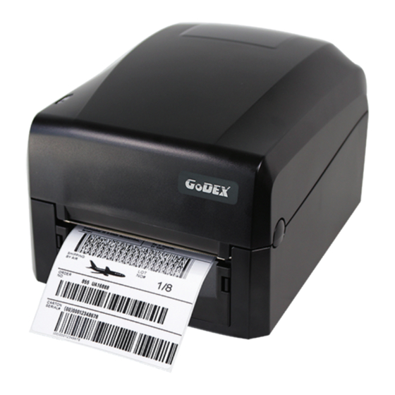
- Page 1 GE300/GE330 THERMAL LABEL PRINTER USER MANUAL User Manual : GE300 series Version : Rev 1.6 Issue Date : 2021.04.07 : 920-017511-00...
-
Page 2: Table Of Contents
GE300/GE330 USER MANUAL CONTENTS Thermal Label Printer Box Content Getting To Know Your Printer Printer Setup Open The Printer Cover Open The Printing Mechanism Loading The Ribbon Loading The Label Roll Installing The Label Supply Hub Connecting The Printer To The Host Computer... - Page 3 GE300/GE330 USER MANUAL FCC COMPLIANCE STATEMENT FOR AMERICAN USERS This equipment has been tested and found to comply with the limits for a Class B digital device, pursuant to Part 15 of the FCC Rules. These limits are designed to provide reasonable protection against harmful interference in a residential installation.
- Page 4 GE300/GE330 USER MANUAL SAFETY INSTRUCTIONS Please read the following instructions carefully. Keep the equipment away from humidity. Before you connect the equipment to the power outlet, please check the voltage of the power source. Make sure the printer is off before plugging the power connector into the power jack.
-
Page 5: Box Content 001
Barcode Printer Box Content Please check that all of the following items are included with your printer. GE300 Thermal Label Printer (Package content and Logo style may vary per region.) Label Supply Module Ribbon Module Label Supply Hub... -
Page 6: Getting To Know Your Printer
Barcode Printer Getting To Know Your Printer Device Overview Front View TOP COVER LED OPERATION PANEL FEED BUTTON LED INDICATOR COVER OPEN BUTTONS Release buttons for opening the printer cover Rear View FAN-FOLD LABEL INSERT Feed slot for continuous labels ETHERNET PORT POWER SWITCH SERIAL PORT... - Page 7 Barcode Printer Open The Printer Cover RELEASE LATCH(Left) RELEASE LATCH(Right) Open The Printing Mechanism PRINT HEAD LABEL GUIDE(Left) LABEL GUIDE(Right) LABEL SENSOR PLATEN...
-
Page 8: Printer Setup
Printer Setup Open The Printer Cover Pressing The Cover Open Buttons Place the printer on a flat surface. Open the printer cover by pressing the release buttons on both sides of the printer housing and lift the cover. Pressing the button Pressing the button COVER OPEN BUTTONS Release buttons for opening the printer cover. -
Page 9: Loading The Ribbon 005
Printer Setup Loading The Ribbon A New Ribbon Module Installation NEW RIBBON EMPTY RIBBON CORE Attach the ribbon to the empty ribbon core with the adhesive strip at the end of the ribbon. Notch on left side Stick on empty ribbon core Wind the ribbon around the empty ribbon core for 2 to 3 circles. - Page 10 Printer Setup Load The Ribbon On The Printer For Ribbon Supply Module RIBBON SUPPLY MODULE Place the right-hand side of ribbon first. Align the ribbon core to the holder HOLDER Push the ribbon to tighten the spring of the holder SPRING OF HOLDER Then place the left-hand side of the ribbon.
- Page 11 Printer Setup Close the printing mechanism to complete the ribbon supply module loading. Close the printing mechanism Load The Ribbon On The Printer For Ribbon Rewind Module RIBBON REWIND MODULE Place the right-hand side of empty ribbon core first. Align the empty ribbon core to the holder Push the empty ribbon core to tighten the spring of the holder...
- Page 12 Printer Setup Then place the left-hand side of the empty ribbon core. Left side Align the notch of empty ribbon core to the spoke NOTCH OF RIBBON CORE SPOKE Turn the ribbon rewind wheel to tighten the ribbon until it has no wrinkles. RIBBON REWIND WHEEL Ribbon loading completed.
-
Page 13: Loading The Label Roll 009
Printer Setup Loading The Label Roll A New Label Roll Module Installation LABEL STOCK LABEL SUPPLY HUB Place the label stock on the label supply hub, attach the label guide plates to the label stock holder. Place on the ribbon hub A label roll module is assembled as below. - Page 14 Printer Setup Load The Label Roll Module On The Printer Release the printing mechanism and lift it. Open the printing mechanism Place the label roll module on the printer. Place on the printer Pass the label through the printing mechanism.
- Page 15 Printer Setup Pass the label through the label guides and adjust the label guide to the label width. The label guide will help to prevent the label swaying. Through the label guides LABEL GUIDES Close the printing mechanism and top cover to complete the label loading. Close the printing mechanism...
- Page 16 Printer Setup Loading The Label Supply Hub 1" Cores Loading the label supply hub for 1" cores. 1.5" Cores Loading the label supply hub for 1.5" cores.
-
Page 17: Connecting The Printer To The Host Computer 013
Connect the power cord to the AC adapter. POWER CORD AC ADAPTER Connect the jack of the power adapter to the printer and connect the plug of the power adapter to the socket of the wall. GE300 THERMAL LABEL PRINTER POWER ADAPTER JACK SLOT THE WALL... - Page 18 Printer Setup Connect the USB/parallel cable to the printer and host computer. GE300 THERMAL LABEL PRINTER USB PORT USB CABLE PLUG PLUG SOCKET Switch on the printer. The LED indicator should now lights up. LED INDICATOR...
-
Page 19: Installing The Driver 015
Printer Setup Installing The Driver Insert the product CD in the CD/DVD drive of the host computer and open the "Seagull Drivers" folder on the CD. Select the icon for the driver file and click it to start the installation. Follow the instructions on the screen. - Page 20 Printer Setup Specify the port used to connect the printer to the host computer. Enter a printer name and assign the appropriate rights. Once the installation is complete, a summary of the printer settings is displayed. Check whether the printer settings are correct and click "Finish" to start copying the driver files. Wait until copying is complete, then finish the installation.
- Page 21 Prin er Setup 7. Once the driver installation is complete, the new printer should appear in the "Printers and Faxes" folder.
-
Page 22: Operation Panel 018
Operation Panel LED Operation Panel LED OPERATION PANEL FEED BUTTON LED INDICATOR FEED Button When you press the FEED button, the printer moves the label to the defined stop position. If you are using continuous labels, pressing the FEED button will move label stock until you release the button again. If you are using individual labels, pressing the FEED button will move only one label. -
Page 23: Error Alerts 019
Operation Panel Error Alerts In the event of a problem that prevents normal functioning of the printer, you will see an error message on LED indicators and hear some beep signals. Please refer to below table for the error alerts. Error Light Colour ... -
Page 24: Label Calibration And Self Test
Operation Panel Label Calibration and Self Test Label Calibration The printer can automatically detect and store label height. That means the host computer does not need to transmit the label height to the printer. Self Test Self-test function lets you check whether the printer is functioning normally. Here is how you run the label size calibration and self test. -
Page 25: Netsetting For Ethernet
NetSetting for Ethernet Installing The NetSetting software The NetSetting software is used to manage the network configurations when connecting the printer via Ethernet port. It is available on product CD or can be downloaded from official website. To install the NetSetting, please follow below steps. -
Page 26: The Interface Of Netsetting 022
PC. Click the magnifier icon to search the Godex printers which are connected via Ethernet port in you network environment. Once a connected Godex printer is detected, it will be listed on the start page. - Page 27 NetSetting for Ethernet IP Setting The IP Setting tab can change the printer name, Port number, Gateway setting and the password for configuring the printer. You can also set the printer’s IP address ether by DHCP or by Static IP. You can press “Set”...
- Page 28 NetSetting for Ethernet Alert Path Setting NetSetting will send the alert messages to designated mail account when the error happened on printer. The alert messages are sent by SMTP (Simple Mail Transfer Protocol) or SNMP (Simple Network Management Protocol). You can set or change the configurations of SMTP and SNMP on this “Alert Path Setting” tab. You can press “Set”...
- Page 29 NetSetting for Ethernet Alert Message Setting For the alert message notification function, you can decide which error cases need to be sent out to the operator. Moreover, the alert messages can be set to be sent by SMTP, SNMP or both. You can press “Set”...
- Page 30 NetSetting for Ethernet Printer Configuration Set or change the configurations of connected printer. Most of key settings for the printer operation can be done by this setting page. You can press “Set” button to apply the settings and “ReGet” button to refresh the setting values.
- Page 31 NetSetting for Ethernet User Command The “User Command” tab provides a communication interface for operator to control the printer. Input printer commands in "Input Command" window and press “Send Command” button, the commands will be sent to the printer. For some commands that will return response message, the message will be displayed in "Output Message" window. You can press “Send Command”...
- Page 32 NetSetting for Ethernet Firmware Download On “Firmware Download” tab, the current version of printer firmware will be showed on the screen. If you need to update the printer firmware, just specify the file location of firmware file and press “Start Download Firmware” button. The printer firmware then can be updated remotely.
-
Page 33: Accessories 029
Accessories Install The Cutter Step 1.Open the top cover and TPH Step 2.Disassemble the front panel. Step 3.Place the connector into the hole(as Step 4.Take off the bottom cover and connect the indicated by the circle) and secure the cutter cable to main board and put on the bottom cover. - Page 34 Accessories Step 5.Pull out the label and pass through the cutter. Step 6.Closed the top cover.
-
Page 35: Maintenance And Adjustment 031
Maintenance And Adjustment Cleaning The Print Head Dirt on the print head or ribbon, or glue residue from the label stock may result in inadequate print quality. The printer cover must therefore always be closed during printing. Keeping dirt and dust away from the paper or labels ensures a good print quality and a longer lifespan of the print head. -
Page 36: Troubleshooting 032
Maintenance And Adjustment Troubleshooting Problem Solution Check the power supply. ♦ The printer is switched on but the LED does not light up. Please see the Section 2.6 Check the software settings (driver settings) or command codes. ♦ ♦ Look for the error alert in the table in Section 3.2. Error Alerts. The LED lights up red and printing is interrupted. - Page 37 * Quick setting only supports GoLabel 1.15K and Arm 7 (FW1.100) Or Arm 9 (FW2.00A) or higher version Set up wireless network through GoDEX WiFi tool Turn on the printer,connect printer and computer by USB cable. Start GoLabel. “Generic”→”Printer Setup”.
- Page 38 APPENDIX Wi-Fi Printer Sever Module Installation(Quick Setting) Click”WiFi Setting”icon. Click”Quick Setting”icon.
- Page 39 APPENDIX Wi-Fi Printer Sever Module Installation(Quick Setting)
- Page 40 APPENDIX Wi-Fi Printer Sever Module Installation(Quick Setting) Select server and click next button. Enter the password set on the server side and click the “Setting” button.
- Page 41 APPENDIX Wi-Fi Printer Sever Module Installation(Quick Setting) After the setting succeeded, a prompt will pop up and the printer will restart. Select the "Other" tab and click the "Get Data" icon after selecting "IP Settings".
- Page 42 APPENDIX Wi-Fi Printer Sever Module Installation(Quick Setting) After remembering the IP address, open the "Printer Settings" window. Select the“Printer Interface”tab, fill in the IP address and click “Save” to complete the setting.
-
Page 43: Appendix
GE300/GE330 USER MANUAL APPENDIX PRODUCT SPENIFICATIONS Model GE300 GE330 Print Method Thermal Transfer/Direct Thermal Resolution 203dpi(8dots/mm) 300dpi(12dots/mm) Print Speed 5 IPS (102mm/s) 4 IPS(76.2 mm/s) Print Width 4.25”(108mm) 4.16”(105.7mm) Print Length Min. 0.16”(4mm)**; Max. 68”(1727mm) Min. 0.16”(4 mm)**; Max. 30”(762mm) - Page 44 ****Minimum print height specification compliance can be dependent on non-standard material variables such as label type, thickness, spacing, liner construction, etc. Godex is pleased to test non-standard materials for minimum height printing capability. *** The cutter is an optional accessory. If the cutter is installed,it is not suitable for children to approach.
- Page 45 Pinout Description Connector Type : Type B Pin NO. Function VBUS Serial Port Default settings Baud rate 9600, no parity, 8 data bits, 1 stop bit, XON/XOFF protocol and RTS/CTS RS232 Housing(9-pin to 9-pin) DB9 Socket DB9 Plug +5V, max 500mA Computer Printer...
Need help?
Do you have a question about the GE300 and is the answer not in the manual?
Questions and answers