Sign In
Upload
Download
Table of Contents
Contents
Add to my manuals
Delete from my manuals
Share
URL of this page:
HTML Link:
Bookmark this page
Add
Manual will be automatically added to "My Manuals"
Print this page
×
Bookmark added
×
Added to my manuals
Manuals
Brands
Godex Manuals
Label Maker
BP1000i Series
User manual
Godex BP1000i Series User Manual
Thermal label printer
Hide thumbs
1
Table Of Contents
2
3
4
5
6
7
8
9
10
11
12
13
14
15
16
17
18
19
20
21
22
23
24
25
26
27
28
29
30
31
32
33
34
35
36
37
38
39
40
41
42
43
44
45
46
47
48
49
50
51
52
53
54
55
56
57
58
59
60
page
of
60
Go
/
60
Contents
Table of Contents
Bookmarks
Table of Contents
Table of Contents
Bp1000I Series
User Manual
Barcode Printer
Box Content 001
Getting to Know Your Printer
Netsetting for Ethernet 031
Installing the Netsetting Software 031
The Interface of Netsetting 032
Accessories 039
Preparation Steps 039
Installing the Cutter 040
Option Rewind Ribbon Hub Removing Ribbon 043
Maintenance and Adjustment 045
Installing / Removing the Print Head Module 045
Adjusting the Print Line 046
Adjusting Ribbon Tension 047
Cleaning the Thermal Print Head 048
Adjusting the Balance and Print Head Tension 049
Ribbon Shield Settings 050
Cutter Settings 051
Appendix
Advertisement
Quick Links
1
User Manual
2
Netsetting for Ethernet 031
Download this manual
User Manual
: BP1000i series
Version
: Rev. 1.1
Issue Date
: 2017.11
P/N
: 920-016211-00
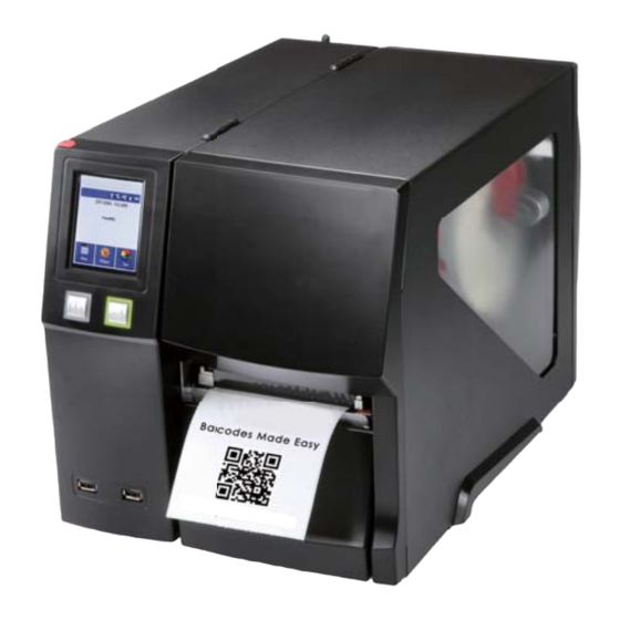
BP1000i Series
THERMAL LABEL PRINTER
USER MANUAL
Table of
Contents
Previous
Page
Next
Page
1
2
3
4
5
Advertisement
Table of Contents
Need help?
Do you have a question about the BP1000i Series and is the answer not in the manual?
Ask a question
Questions and answers
Related Manuals for Godex BP1000i Series
Label Maker Godex BZB-2U User Manual
(14 pages)
Label Maker Godex MX3 series: MX30 Manual
Thermal label printer (13 pages)
Label Maker Godex BP700 Series User Manual
Thermal label printer (80 pages)
Label Maker Godex BP1300i User Manual
Thermal label printer (60 pages)
Label Maker Godex EZ-4TT Plus User Manual
Label printer (17 pages)
Label Maker Godex LZX400i User Manual
(76 pages)
Label Maker Godex GE300 User Manual
Thermal label printer (45 pages)
Label Maker Godex EZ6000i Series User Manual
Thermal label printer (67 pages)
Label Maker Godex ZX1000i Series User Manual
Thermal label printer (73 pages)
Label Maker Godex DT200 Series User Manual
(55 pages)
Label Maker Godex ZX400+ Series User Manual
Thermal label printer (89 pages)
Label Maker Godex Stand Alone Printer Instruction Manual
(3 pages)
Label Maker Godex ZX1000i Series User Manual
Thermal label printer (89 pages)
Label Maker Godex DT4C User Manual
(38 pages)
Label Maker Godex HD830i Quick Manual
Thermal label printer (8 pages)
Label Maker Godex DT Series User Manual
(39 pages)
This manual is also suitable for:
Bp1200i
Bp1300i
Bp1600i
Table of Contents
Print
Rename the bookmark
Delete bookmark?
Delete from my manuals?
Login
Sign In
OR
Sign in with Facebook
Sign in with Google
Upload manual
Upload from disk
Upload from URL


Need help?
Do you have a question about the BP1000i Series and is the answer not in the manual?
Questions and answers