Table of Contents
Advertisement
Advertisement
Table of Contents

Related Manuals for Godex LZX400i


Summary of Contents for Godex LZX400i
- Page 1 USER MANUAL ZX400/ZX400i Version : Rev.A Issue Date : 2016.11 : 920-016411-00...
-
Page 2: Table Of Contents
CONTENTS Barcode Printer ....................................1 1-1 Box Content ....................................1 1-2 Getting To Know Your Printer ............................... 2 2. Printer Setup ......................................5 2-1 Loading the label roll ..................................5 2-2 Loading & Removing the Ribbon ..............................9 2-3 Connecting The Printer To The Host Computer ........................11 2-4 Wizard CD Standard Installation .............................. - Page 3 ZX400/ZX400i FCC COMPLIANCE STATEMENT FOR AMERICAN USERS Federal Communication Commission Interference Statement This equipment has been tested and found to comply with the limits for a Class B digital device, pursuant to Part 15 of the FCC Rules. These limits are designed to provide reasonable protection against harmful interference in a residential installation.
- Page 4 SAFETY INSTRUCTIONS Please read the following instructions carefully. Keep the equipment away from humidity. Before you connect the equipment to the power outlet, please check the voltage of the power source. Make sure the printer is off before plugging the power connector into the power jack.
-
Page 5: Barcode Printer
1. Barcode Printer 1-1 Box Content Please check that all of the following items are included with your printer. (Package content and Logo style may vary per region。) Barcode Printer ZX420i ZX420 Label Stock USB Cable Quick Guide ... -
Page 6: Getting To Know Your Printer
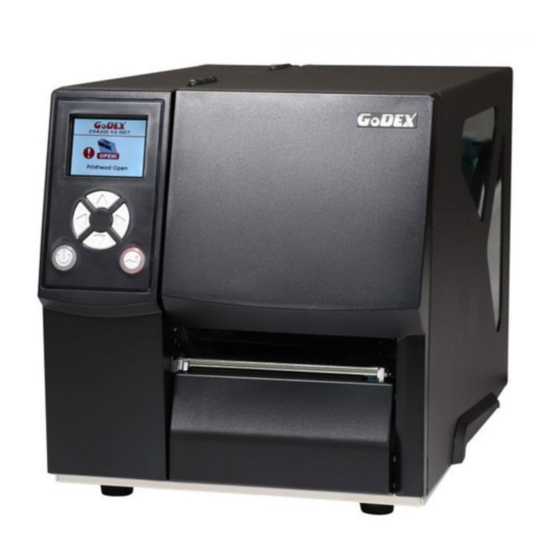
1-2 Getting To Know Your Printer (ZX420i) Front View TOP COVER LCD PANEL OPERATOR PANEL VIEWING WINDOW POWER BUTTON FEED BUTTON FRONT COVER Rear View AUTO-CALIBRATION BUTTON BT/Wi-Fi PORT (OPTIONAL) RS232 PORT USB PORT USB HOST (OPTIONAL) PARALLEL PORT (OPTIONAL) POWER JACK EXTERNAL LABEL INSERT... - Page 7 (ZX420) Front View TOP COVER VIEWING WINDOW POWER BUTTON FEED BUTTON FRONT COVER Rear View AUTO-CALIBRATION BUTTON BT/Wi-Fi PORT (OPTIONAL) USB PORT PARALLEL PORT (OPTIONAL) POWER JACK EXTERNAL LABEL INSERT...
- Page 8 Open The Printer Cover PAPER GUIDE RIBBON REWIND HUB RIBBON SUPPLY HUB HANDLE OF PAPER GUIDE PRINT MECHANISM PLATEN ROLLER LABEL ROLL GUIDE RELEASE LEVER FOR PRINT HEAD RELEASE LEVER FOR PRINT HEAD ADJUSTABLE SENSOR PAPER GUIDE ...
-
Page 9: Printer Setup
2. Printer Setup 2-1 Loading the label roll This printer supports the following printing methods: Thermal transfer printing (TTP):Requires a ribbon for transferring a printed image to a medium. Direct thermal printing (DTP):Does not require a ribbon, only thermal paper. Please check which printing method you are using and alter the settings accordingly in the printer driver, printer menu, and/or software. - Page 10 Now fold the label roll guide up Place the label roll on the label supply hub, pushing it right up to the printer housing. (Do not apply too much pressure to avoid damaging the label stock.)
- Page 11 Load the label roll into the printer as shown in the illustration. Pass it through the printer as indicated by the red arrows. Pass the label stock through the adjustable Sensor and up to the tear-off plate.
- Page 12 2. Return the print head release lever to its original position. 1. The labels pass between the wall of the printer housing and the adjustable paper guide. Then close the printer cover.
-
Page 13: Loading & Removing The Ribbon
2-2 Loading & Removing the Ribbon Loading Ribbon Place the printer on a flat surface and open the printer cover Place a new ribbon on the ribbon supply hub. The illustration as below shows you how to install the ribbon. Ink side out... - Page 14 Pass the ribbon under the print head and back up on the other side. Attach it to the empty ribbon core.
-
Page 15: Connecting The Printer To The Host Computer
2-3 Connecting The Printer To The Host Computer Please make sure that the printer is switched off. Connect the power cord to the AC adapter and connect the adapter to the printer. Connect the USB / parallel cable to the printer and host computer. (The type of cable may vary according to the products which you purchase.) ... -
Page 16: Wizard Cd Standard Installation
2-4 Wizard CD Standard Installation Step.01 Insert the Super Wizard CD in the CD/DVD drive of the host computer and the installation program should pop up automatically. You will see the Welcome screen first. On the Welcome screen, choose “STANDARD INSTALLATION”. Step.02 The wizard will then ask you to make sure your USB and power cables are connected and that the power is turned on. - Page 17 Step.04 As the printer driver and GoLabel are installing, a screen will display a progress bar. While downloading completed you will see Installation completed. Click “NEXT” to continue. You can also print a test label. If don’t print a test label, the screen display as step 6. Step.05 NOTE If you need more resources, tools or reference documents, you can also find them on Super Wizard CD.
- Page 18 Step.06 Once the installation is complete, you can start to make and print labels with GoLabel or through the printer driver.
-
Page 19: Wizard Cd Other Choice Installation
2-5 Wizard CD Other Choice Installation Click “OTHER CHOICES” to next screen and select “PRINTER DRIVERS”. Step.01 Click “INSTALL SEAGULL SCIENTIFIC WINDOWS DRIVER” to next screen, and click “NEXT”. Step.02 Select “I accept the terms in the license agreement”, and click ”Next”,then click ”Finish” to step 4. Step.03... - Page 20 Step.04 The Driver Wizard will guide you through the installation procedure. Select "Install printer drivers" and click “Next”. Step.05 With a USB connection, search models such as the right diagram printer device. Specify your printer model and click ”Next”. Step.06 Enter the printer name (you can use default), then click "Next"...
-
Page 21: Operation Panel
3. Operation Panel 3-1 LED Operation Panel (For ZX400i Series) LCD PANEL OPERATOR PANEL OPERATOR PANEL FEED BUTTON POWER BUTTON POWER Button Press the POWER button to turn on the printer, and the START UP SCREEN appears. The printer is on “ready to print” status, the LCD screen should display the message “READY“... -
Page 22: Feed Button
(For ZX400 Series) FEED BUTTON POWER BUTTON POWER Button Press the POWER button to turn on the printer, and the START UP SCREEN appears. The printer is on “ready to print” status. When printer is turned on, hold and press down the POWER button for 3 second will turn the printer off. FEED Button Turn on the printer and press the FEED button. -
Page 23: Lcd Interface Introduction
3-2 LCD Interface Introduction Getting Started Press the POWER button to turn on the printer, and the START UP SCREEN appears. Power on If the printer is on “ready to print” status, the LCD screen should display the message “Ready“ on the screen. Please keep pressing button and wait for the timer to be filled, then the LCD interface will enter into the MAIN PAGE for SETTING MODE. - Page 24 Operations on Setting Page On MAIN PAGE, press button to move the cursor and select the functions. Select a designated function and press FEED button, you will enter the SETTING PAGES for the function. Select Enter On SETTING PAGES, press button to select the setting items.
- Page 25 On SETTING VALUE PAGES, press button to change the setting values. Select Press FEED button will apply the setting value you just selected, and the red tick will appear to mark the value. Apply NOTE The blue arrow indicates the value you are selected. ** The red tick indicates that the selected value is applied now.
- Page 26 Exit from Current Page to Ready Status The icon on top-left corner displays the capture of upper level screen and also guides you back to upper level with left or up arrow. NAVIGATION ICON On SETTING VALUE PAGES, press Back to the Setting On SETTING PAGES, press button will go back to the MAIN PAGE screen.
- Page 27 On MAIN PAGE, select the “EXIT” icon and press the FEED button to exit from SETTING MODE and the printer goes back to READY status. EXIT from Setting Mode Back to the Ready status...
-
Page 28: Lan Setting
3-3 LAN Setting Operations on Setting Page On MAIN PAGE, press button to move the cursor and select the functions. Select a designated function and press FEED button, you will enter the SETTING PAGES for the function. Select Enter LAN Setting On LAN Setting PAGE, press button to select the setting items. - Page 29 The default of DHCP is Disable. Press button to change the setting values. Select to enable DHCP Press FEED button twice to save the setting. Press FEED once to exit Press FEED again to save and return to previous SETTING PAGE...
-
Page 30: Lcd Password
3-4 LCD Password Operations on Setting Page On MAIN PAGE, press button to move the cursor and select the functions. Seclect a designated function and press FEED button, you will enter the SETTING PAGE for the Select Device Enter LCD Password The default of LCD Setting is Disable. - Page 31 Select button again to setup the password Press FEED button twice to save the setting Press FEED button once to exit Press FEED button again to save and return to previous SETTING PAGE...
-
Page 32: Lcd Interface Function
3-5 LCD Interface Function Main Page Setting items for printer, ex. Printing speed, darkness. Printer Also includes a Printing Wizard for your ease of printing. Setting items for printing label, ex. Rotation, Printing position offset. Label Option modules and connection port settings. Device Self-Diagnose functions for printer, ex. - Page 33 Status of LCD Interface When printer is on standby status (ready to print), the LCD interface will display “Ready” on screen. You can only print on this “Ready“ status. If there is any printers error, the LCD screen will display the error screen to show the type of error. You can fix the error according the notice.
-
Page 36: Label Size Calibration And Self Test Page
3-6 Label size calibration and Self Test Page The printer can automatically detect and store label height. That means the host computer does not need to transmit the label height to the printer. And the self-test function lets you check whether the printer is functioning normally. Here is how you run the label size calibration and self test. - Page 37 Label Calibration Button A hardware button to make a Label Calibration while printer encountering ‘’Media Error’’ during the cases when first-time printer start up or change label or ribbon to another type, such as change using gap label to continuous or black mark labels.
-
Page 38: Error Alerts
3-7 Error Alerts (For ZX400i Series) In the event of a problem that prevents normal functioning of the printer, you will see an error message on LED indicators and hear some beep signals. Please refer to below table for the error alerts. LCD TOUCH PANEL OPERATION TOUCH PANEL... - Page 40 (For ZX400 Series) In the event of a problem that prevents normal functioning of the printer, you will see an error message on LED indicators and hear some beep signals. Please refer to below table for the error alerts. FEED BUTTON (Status Indictor) POWER BUTTON (Power Indictor)
- Page 41 Please make sure that the gap sensor is positioned correctly. If Unable to detect that does not fix the problem, the paper. run the auto-detection function check again. media beeps The labels are Replace the label roll. finished. Paper jam. Check the path of paper feeding.
-
Page 42: Usb Host
USB memory stick : It supports hot-plugging function; printer will create a Folder ‘’\LABELDIR’’ and switch ‘’User Flash’’ to ‘’ Extended Memory‘’ automatically while user plugs an USB memory stick into a GoDEX printer. Connect the USB Stick plugged -in printer to PC via USB Device or Ethernet port and run ‘’GoLabel’’ software to download Graphic, Font, Label Format, DBF and Command files to the printer. - Page 43 LCD touch panel and wait for data input. The USB Host port on GoDEX printer is without ‘’HUB’’ function. The USB Memory Stick supports with ‘’FAT32’’Disk Format and up to 32GB only. The certified venders are Transcend, Apacer, Patriot, Consair and Kingston.
-
Page 44: Netsetting For Ethernet
4 NetSetting for Ethernet 4-1 Installing the NetSetting software The NetSetting software is used to manage the network configurations when connecting the printer via Ethernet port. It is available on product CD or can be downloaded from official website. To install the NetSetting, please follow below steps. - Page 45 Step.05 Once the installation is completed, you will see the NetSetting icon on your desktop as right diagram.
-
Page 46: The Interface Of Netsetting
4-2 The Interface of NetSetting GoDEX printer can also be used through a network connection (as a remote network printer), make sure the printer connected to the Internet and the power cord, you can use the Interface of NetSetting to search connected network printers. - Page 47 IP Setting The IP Setting tab can change the printer name, Port number, Gateway setting and the password for configuring the printer. You can also set the printer’s IP address ether by DHCP or by Static IP. You can press “Set” button to apply the settings and “ReGet” button to refresh the setting values. NOTE * To fully benefit from the NetSetting software, you should be familiar with basic networking principles.
- Page 48 Alert Path Setting NetSetting will send the alert messages to designated mail account when the error happened on printer. The alert messages are sent by SMTP (Simple Mail Transfer Protocol) or SNMP (Simple Network Management Protocol). You can set or change the configurations of SMTP and SNMP on this “Alert Path Setting” tab. You can press “Set”...
- Page 49 Alert Message Setting For the alert message notification function, you can decide which error cases need to be sent out to the operator. Moreover, the alert messages can be set to be sent by SMTP, SNMP or both. You can press “Set” button to apply the settings and “ReGet” button to refresh the setting values.
-
Page 50: Printer Configuration
Printer Configuration Set or change the configurations of connected printer. Most of key settings for the printer operation can be done by this setting page. You can press “Set” button to apply the settings and “ReGet” button to refresh the setting values. - Page 51 User Command The “User Command” tab provides a communication interface for operator to control the printer. Input printercommands in "Input Command" window and press “Send Command” button, the commands will be sent to the printer. For some commands that will return response message, the message will be displayed in "Output Message" window. You can press “Set”...
-
Page 52: Firmware Download
Firmware Download On “Firmware Download” tab, the current version of printer firmware will be showed on the screen. If you need to update the printer firmware, just specify the file location of firmware file and press “Start Download Firmware”button. The printer firmware then can be updated remotely. -
Page 53: Accessories
5 Accessories 5-1 Preparation Steps Before installing the optional modules, please make some preparations as follows. Turn off the printer : Remember to switch off the printer before installing any module. Open the printer cover NOTE Remember to switch off the printer before installing the cutter. ** Do not use to cut adhesive labels! Glue residue will be left on the cutter blade and impair its functioning. -
Page 54: Installing The Cutter
5-2 Installing the Cutter 5-2-1 Installing the Guillotine Cutter Overview Of Guillotine Cutter CONNECTION CABLE OF GUILLOTINE CUTTER COVER Steps for installing the Guillotine Cutter: (Power off the printer and remove the power cable before installing the guillotine cutter module) Remove the screw (as circle indicated). - Page 55 2. Remove the cover panel by pushing to right-hand side. 3. Stick the hub onto the circled area. 4. Direct the cutter’s cable through the platen bracket of the printer. 5. Engage the catchs of the cutter module firmly into the printer.
- Page 56 6. Tighten the screws and plug the cutter’s cable into the printer in the direction of the arrow. 7. Put the cable into the hub. Close printer cover. NOTE * Printer power should be off when plugging the connector to avoid malfunction...
-
Page 57: Installing The Rotary Cutter
5-2-2 Installing the Rotary Cutter Overview Of Rotary Cutter CONNECTION CABLE OF ROTARY CUTTER COVER Steps for installing the Rotary Cutter: (Power off the printer and remove the power cable before installing the guillotine cutter module) 1. Remove the screw (as circle indicated). NOTE Power off the printer and remove the cable from the connector before installing rotary cutter module. - Page 58 2. Remove the cover panel by pushing to right-hand side. 3. Stick the hub onto the circled area. 4. Direct the cutter’s cable through the platen bracket of the printer. 5. Engage the catchs of the cutter module firmly into the printer.
- Page 59 6. Plug the cutter’s cable into the printer in the direction of the arrow. 7. Put the cable into the hub. Close printer cover. NOTE * Printer power should be off when plugging the connector to avoid malfunction...
-
Page 60: Installing The Label Dispenser
5-3 Installing The Label Dispenser The Overview of the Label Dispenser CONNECT CABLE OF LABEL DISPENSER SCREWS PAPER SENSOR Steps for installing the Label Dispenser: (Power off the printer and remove the power cable before installing the label dispenser module) 1. - Page 61 2. Remove the cover panel by pushing to right-hand side. 3. Stick the hub onto the circled area. 4. Direct the label dispenser’s cable through the platen bracket of the printer. 5. Engage the catchs of the label dispenser module firmly into the printer.
- Page 62 6. Plug the label dispenser’s cable into the printer in the direction of the arrow. 7. Put the cable into the hub. 8. Close printer cover. NOTE * Printer power should be off when plugging the connector to avoid malfunction...
-
Page 63: Maintenance And Adjustment
Maintenance and Adjustment 6-1 Installing / removing the print head module 1. Open the printer cover. 2. Using a screwdriver or a coin, loosen the screw to take out the TPH module. 3. Turn the print head counterclockwise to a top right position 4. -
Page 64: Adjusting The Print Line
6-2 Adjusting the print line 1. Open the printer cover. 2. Using a screwdriver or a coin to loosen the screw 3. Turn the print head counterclockwise to a top right position If no improvement is visible, turn the screws(A) clockwise or counterclockwise as far as possible and be sure to align with the indicator board and indicator line. -
Page 65: Adjusting Ribbon Tension
6-3 Adjusting ribbon tension You can adjust the ribbon tension by turning the ribbon shaft knob (see illustration) clockwise or counterclockwise. There are 4 possible settings, which is marked on the ribbon supply hub. # 1 : Tension is the highest # 4 : Tension is the lowest If the tension is so low that the ribbon does not move forward, you need to reduce the tension of the ribbon supply hub. -
Page 66: Cleaning The Thermal Print Head
6-4 Cleaning the thermal print head Dirt on the print head or ribbon may result in inadequate print quality (there are only partial images on the label). The printer cover should therefore be kept closed when possible. Keeping dirt and dust away from the paper or labels ensures a good print quality and a longer lifespan of the print head. -
Page 67: Adjusting The Balance And Print Head Tension
6-5 Adjusting the balance and print head tension 1. Open the printer cover. 2. Using a screwdriver or a coin to loosen the screwcoin to loosen the screw When using a variety of label stock and ribbons, the ink may not be evenly distributed. If there is no printed image on one side of the paper, or the ribbon wrinkles, the print head pressure must be readjusted using the TPH spring boxes. -
Page 68: Ribbon Shield Settings
6-6 Ribbon shield settings The use of different ribbon materials may cause wrinkling of the ribbon, which in turn affects the print result as illustrated by the examples in (a) and (b). To change the print quality, you can adjust the ribbon shield screws. If your print result looks like the example in (a), you need to turn ribbon shield screw clockwise. -
Page 69: Cutter Settings
6-7 Cutter settings Switch off the printer before removingthe CUTTER. (Remove or install cutter refer to ‘’accessories’’ in Section 5) Unscrew the screw at the bottom of cutter . Remove the cutter cover. Clean and remove jammed paper. Reinstall CUTTER back onto printer. NOTE Remember to switch off the printer before removing the CUTTER. -
Page 70: Troubleshooting
6-8 Troubleshooting NOTE * If any problems occur that are not described here, please contact your dealer. - Page 71 ** Minimum print height and maximum print speed specification compliance can be dependent on non-standard material variables such as label type, thickness, spacing, liner construction, etc. GoDEX is pleased to test non-standard materials for minimum print height, and maximum print speed capability.
- Page 72 APPENDIX- INTERFACE...
- Page 73 ZX400(i)/BPZ400(i) Series 無線網路安裝說明 ZX400(i)/BPZ400(i) Series Wi-Fi Module Installation Step 4. Step 2. Step 3. Step 1. Step 8. Step 7. Step 6. Step 5. Wi-Fi Wi-Fi...
- Page 74 ZX400(i)/BPZ400(i) Series 藍牙模組安裝說明 ZX400(i)/BPZ400(i) Series BlueTooth Module Installation Step 1. Step 2. Step 3. Step 4. Step 6. Step 5. Step 8. Step 7. Wi-Fi...
- Page 75 ZX400(i)/BPZ400(i) Series 並列傳輸模組安裝說明 ZX400(i)/BPZ400(i) Series Parallel module Installation Step 1. Step 3. Step 2. Step 4. Step 5. Step 8. Step 7. Step 6.
- Page 76 L’utilisation d’accessoires autres que ceux recommandé s ou des changements à ce produit qui ne sont pas approuvé s par GoDEX International Co.,Ltd. peuvent annuler la conformité de ce produit et mettre fin au droit qu’a l’usager d’utiliser l’é quipement.
Need help?
Do you have a question about the LZX400i and is the answer not in the manual?
Questions and answers