
Related Manuals for SICK ZIRKOR302 P


Summary of Contents for SICK ZIRKOR302 P
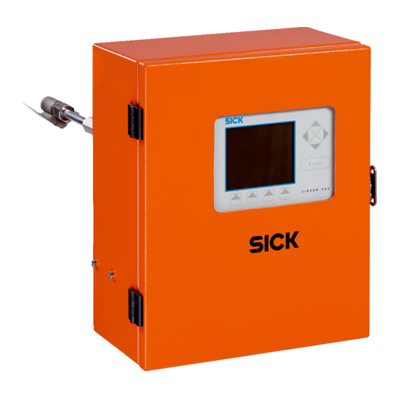
- Page 1 O P E R A T I N G I N S T R U C T I O N S ZIRKOR302 P Oxygen Analyzer Standalone Version with Measuring Gas Pump...
-
Page 2: Table Of Contents
Table of contents Docu No. DLT6230-07_eng_0017 General Purpose of this Document Operating Personnel Other Documents Obligations and Liability Safety Symbols Intended Use Incorrect Usage Informal Safety Measures Danger from Electrical Power 1.10 Hazardous Areas 1.11 Removal from Service 1.12 Alterations to the Construction of Devices General Description Theoretical Fundamentals and Measuring Principle Functional Description... - Page 3 Table of contents Docu No. DLT6230-07_eng_0017 Causes of Faults Causes of Warnings Internal Electronics Fault Service and Maintenance Recommendations for practical application Checking and Calibration the Probe Check with Test Gas Software Update to 5V006 with Flash-Update-Software V1.2 Removing the Gas Extraction Device and Checking Penetrability Removing the Probe Body Checking the Measuring Cell Heaters Replacing the Measuring Cell and Measuring Cell Heater...
-
Page 4: General
General - Purpose of this Document General Purpose of this Document These operating instructions provide operators with information about: Operation Safety instructions Maintenance Troubleshooting Although other documents (e.g. Product Information) may provide additional information, they must not be regarded as a substitute for these operating instructions. Operating Personnel For certain activities (electrical installation, for example), specialist knowledge is required. -
Page 5: Obligations And Liability
General - Obligations and Liability Obligations and Liability Observe notes in these operating instructions Before you can operate the device safely and properly, you must be familiar with the basic safety precautions and regulations. These operating instructions (in particular the safety precautions) must be observed by everyone who uses the LAMBDA TRANSMITTER P oxygen analyzer and connected components. -
Page 6: Safety Symbols
General - Safety Symbols Safety Symbols The following designations and symbols for hazards, warnings, and information are used in these operating instructions: DANGER Indicates potential danger for personnel, particularly due to electrical equipment. WARNING Indicates potential danger for personnel due to incorrect handling of system components. -
Page 7: Incorrect Usage
General - Incorrect Usage Incorrect Usage It is forbidden to use the device in any other way than described above. Incorrect usage can be hazardous. If the measuring system is to be used in any other application in which its proper functioning cannot be ensured, consult the manufacturer beforehand. -
Page 8: Danger From Electrical Power
General - Danger from Electrical Power Danger from Electrical Power DANGER The LAMBDA TRANSMITTER P system components are designed for use in industrial power installations. When working on power connections or on live components, make sure that the power supply is switched off. Before reconnecting the power supply, install any shock protection devices that may have been removed. -
Page 9: General Description
General Description - Theoretical Fundamentals and Measuring Principle General Description Theoretical Fundamentals and Measuring Principle The O measuring cell essentially comprises a zirconium dioxide solid electrolyte tube, which is sealed at one end. The internal and external surface is coated with layers of precious metal as electrodes. - Page 10 General Description - Theoretical Fundamentals and Measuring Principle The negative oxygen ion flow is transported to the positive internal electrode and is discharged to form molecular oxygen. A linear correlation exists between the ionic current, which is measured as the probe current signal, and both the oxygen concentration and sample gas quantity that passes through the cell in each time unit.
- Page 11 General Description - Theoretical Fundamentals and Measuring Principle The temperature of the solid electrolytes and the electrodes is not explicitly incorporated in the probe signal, although it does determine the internal resistance of the probe or its limit current and, in turn, the measurable oxygen concentration range. The probe temperature doesn’t need to be measured or regulated, but it must be ensured that it does not undershoot a defined critical value, which depends on the required measurement range.
-
Page 12: Functional Description
General Description - Functional Description Functional Description 2.2.1 General Functional Description The LAMBDA TRANSMITTER P is a versatile microprocessor-based O measuring device for taking direct measurements of the O concentration of gases in the hyperstoichiometric range (λ >1). The measuring method is based on the tried-and- tested ZrO current measuring principle. - Page 13 General Description - Functional Description 2.2.3 Influence of air humidity on the O calibration value The calibration procedure takes place by ambient air. In order to consider the relative humidity of the air used for the calibration procedure a calibration offset (parameter 297) has to be set.
- Page 14 General Description - Functional Description Due to the linear characteristic curve with fixed zero cycle the calibration offset is applied at high O2 values higher than 10%. I [mA] 850 °C 1,560 °F 800 °C 1 470 °F Inflluence of the (0.13 gal/hr) Test gas calibration offset...
- Page 15 General Description - Functional Description 2.2.4 Flow Rate Compensation The flow rate through the capillary depends on the average molecular weight/gas constants of the gas to be measured. With "normal" flue gases from oil, gas, and coal firing, the effect on the measurement accuracy is insignificant. The measurement error is within the specified measurement accuracy of ±...
- Page 16 General Description - Functional Description 2.2.5 Cold-Start Delay The LAMBDA TRANSMITTER P oxygen analyzer features an intelligent cold-start delay function, which prevents flue gas from passing through a cold probe. The optimum time for switching on the measuring gas pump is governed by the temperature of the zirconium dioxide measuring cell, which is determined by measuring the internal cell resistance during the warm-up phase.
- Page 17 General Description - Functional Description 2.2.6 Cold start Ri-table (Parameter 1984..1999) During the cold start the internal resistance (Ri) is measured, in order to recognize the heating condition of the probe. The determinde values are put in the cold start Ri- table.
- Page 18 General Description - Functional Description 2.2.10 Calibration drift history (Parameter 3600...3679) In this history is stored the change of the O2-value of the last 40 automatic calibrations, together with the time (operation hours), so that e.g. the probe drift with a cyclic calibration every 24 hours for the last 40 days is available.
-
Page 19: General View
General Description - General View General View Fig. 2-5: LAMBDA TRANSMITTER P 1 Electronics section 2 Probe section Fig. 2-6: LAMBDA TRANSMITTER P installed on the flue gas duct (side view) 1 Electronics section 5 Protective pipe for gas extraction device, with sintered metal pre-heater 2 Flange 6 Gas extraction device (GED) - Page 20 General Description - General View Display/control unit (optional) Lock for opening the electronics section Additional Operating/fault mode display via LED’s, multi-function key, maintenance switch RS422/CAN/LSB communication LEDs Processor card LEDs for fuse monitoring Fig. 2-7: In sheet-steel housing (front view of RS232 PC interface for connecting electronics section) the remote display software...
-
Page 21: Probe Section View
General Description - Probe Section View Probe Section View Fig. 2-9: Probe section (side view) 1 Connections for differential pressure 5 Measuring gas outlet sensor 6 Exhaust device and flue gas return 2 Connection for air calibration 3 PT100 temperature measuring element measuring cell (inside) Fig. - Page 22 General Description - Probe Section View Fig. 2-11: Connections 1 Free cable connection (e.g. for analog output, RS232 interface cable, additional modules) 2 Drain plug for condensate tank (see Note) 3 Calibration gas inlet 4 Condensat outlet 5 Connection for LSB BUS 6 Connection for LSB BUS 7 Power terminal NOTE...
-
Page 23: Gas Extraction Device
General Description - Gas Extraction Device Gas Extraction Device 2.5.1 View of Gas Extraction Device (GED) Fig. 2-13: Detailed view of gas extraction device 1 Gas extraction device (GED) 2 Sampling filter 3 Sintered metal pre-filter 2.5.2 Measure Gas Temperature Up to 700°C (1300°F) Test gas temperature up to 700 °C (1300°F) (standard) Capillary tube:... - Page 24 General Description - Gas Extraction Device IMPORTANT! In double-wall stacks, a heater for the gas extraction device is required. With flue gases that are 100% saturated (exhaust vapors), a sintered metal pre-filter must also be used. Meas. gas Fig. 2-14: Installation planning aid, max.
-
Page 25: Protective Pipe With Aluminum Core
General Description - Protective Pipe with Aluminum Core IMPORTANT! With horizontal installation, it is recommended that the protective pipe for the gas extraction device be supported as of the following gas extraction device lengths. • Standard: > 1000 mm (39,4 in) •... -
Page 26: Installation
Installation - Prerequisites Installation Prerequisites Before installation, the following points must be taken into account: Measuring location The measuring location must be easily accessible. The weight of the LAMBDA TRANSMITTER P is about 30kg. No condensate must be allowed to form in the gas extraction device. The temperature Test gas temperature along the entire length of the gas extraction device must, therefore, be above the dew point. -
Page 27: Installing The Counterflange
Installation - Installing the Counterflange Installing the Counterflange 1. Plan the mounting position. It can be mounted in any position between the –20° of the vertical axis to the horizontal axis. Connection side below. Fig. 3-1: Mounting position 2. Flame-cut a hole with a diameter of 125mm (4,9 inch) in the flue gas duct. WARNING When you create the apertures, parts that fall into the duct may cause damage. -
Page 28: Installing The Gas Extraction Device (Ged) And Protective Pipe
Installation - Installing the Gas Extraction Device (GED) and Protective Pipe Installing the Gas Extraction Device (GED) and Protective Pipe Installation steps of the gas extraction device and the gas extraction device. Fig. 3-3: Installing the gas extraction device and protective pipe for the gas extraction device (work steps specified) -
Page 29: Installing The Lambda Transmitter P Oxygen Analyzer
Installation - Installing the LAMBDA TRANSMITTER P Oxygen Analyzer Installing the LAMBDA TRANSMITTER P Oxygen Analyzer CAUTION! Observe the line voltage !!! Factory default is AC230V. For changing over to AC115V see chapter 12.4.1 IMPORTANT! The LAMBDA TRANSMITTER P oxygen analyzer must only be operated when the ambient temperature is between -20 °C and +55 °C (4…130°F). -
Page 30: System Settings In Accordance With System Composition (Reduced To Case Studies)
Installation - System Settings in Accordance with System Composition (Reduced to Case System Settings in Accordance with System Composition (Reduced to Case Studies) System Composition System Settings in the Transmitter on power supply unit for GED heater Filter RS42 Optional Par 121 DIP switch heater... -
Page 31: Installing The Gas Extraction Device And Pre-Filter Heater (Optional)
Installation - Installing the Gas Extraction Device and Pre-Filter Heater (Optional) Installing the Gas Extraction Device and Pre-Filter Heater (Optional) j (2x) k (2x) Fig. 3-4: Components of the gas extraction device and pre- filter heater a GED with sampling filter h Safety device for protective pipe incl. - Page 32 Installation - Installing the Gas Extraction Device and Pre-Filter Heater (Optional) 1. Attach the connection flange (f) to the Lambda Transmitter P. Use the M8x35 screws provided. Use flange seal DN80 (type 657 R 3540) without holes (not flange seal (g)). 2.
- Page 33 Installation - Installing the Gas Extraction Device and Pre-Filter Heater (Optional) 3.6.1 Power pack of the gas extraction device and pre-filter heater CAUTION! Observe the line voltage !!! Factory default is AC230V. For changing over to AC115V see chapter 3.6.4 A separate power pack is required to electrically heat the gas extraction device and the sintered metal pre-filter.
- Page 34 Installation - Installing the Gas Extraction Device and Pre-Filter Heater (Optional) 3.6.2 Connectors of the power pack Power connection 4-pins: 7-pin LSB/CAN connection to AC230V/50...60Hz, or LAMBDA TRANSMITTER P AC115V/50...60Hz 7-pin LSB/CAN connection to (Changing trafo plug to other devices with a LSB/CAN terminal Exchanging F1, see 4.6.3)
- Page 35 Installation - Installing the Gas Extraction Device and Pre-Filter Heater (Optional) 3.6.3 Electronics Board of the Power Pack Main fuse line voltage Fuse print trafo Fuse heating Trafo connector primary winding, if line voltage = AC230V Bypass connector, if line voltage = AC230V Trafo connector primary winding, if line voltage = AC115V Electrically connection for line voltage Electrically connection for line voltage SYSTEM BUS...
- Page 36 Installation - Installing the Gas Extraction Device and Pre-Filter Heater (Optional) 3.6.5 Function of the LEDs on the Power Pack Board: Interface LEDs 2 and 4 green = receive, yellow = send. When operating normally, the gas extraction device heater sends a short data packet every two seconds, (i.e.
- Page 37 Installation - Installing the Gas Extraction Device and Pre-Filter Heater (Optional) 3.6.7 Electrical connection at LAMBDA TRANSMITTER P Elec. connection GED Line voltage via 1 LAMBDA TRANSMITTER P und pre filter heater 4p.-plug connector 2 Connection flange for GED heater cable length 2m (6,5 ft) 3 Counterflange LSB / CAN via 7p.-...
- Page 38 Installation - Installing the Gas Extraction Device and Pre-Filter Heater (Optional) 3.6.9 Cable connector for extension the GED and pre filter heater 2-pole (for pre filter heater): Lenght 100mm (3,9 in) External diameter 24mm (0,9 in) Conductor 2,5 sqmm Diameter cond. min 5mm, max 12,5mm, Item no.
-
Page 39: Installing The High-Dust Protective Pipe
Installation - Installing the High-Dust Protective Pipe Installing the High-Dust Protective Pipe Fig. 3-8: Components of the high- dust protective pipe a Counterflange M8x25 hexagon-socket screws with spring washer for securing the adapter b Flange seal for counterflange flange to the counterflange c Protective pipe for high-dust g Standard flange seal for the adapter applications... - Page 40 Installation - Installing the High-Dust Protective Pipe 1. Push the flange seal (b) over the threaded rods of the counterflange. The counterflange must already be welded onto the flue gas duct. 2. Screw the protective pipe for high-dust applications (c) into the adapter flange (d). 3.
-
Page 41: Operation And Display Controls
Operation and Display Controls - Multi-Function Key Operation and Display Controls Multi-Function Key All the basic functions can be executed by means of the multi-function key and maintenance switch. Fig. 4-1: Operation and display unit on the processor board 1 DIP switch 3 Maintenance switch S1 3a = "ON"... -
Page 42: Led-Display
Operation and Display Controls - LED-Display LED-Display Legend: LED Flashes Lights up LED 1 Maintenance Normal operation Maintenance mode active LED 2 — — LED 3 LED 4 Heater monitoring Heater control active Heater with fixed voltage LED 5 Operation mode display Calibration Measurement LED 6... -
Page 43: Monitor Output / Dip Switch On Processor Card
Operation and Display Controls - Monitor Output / DIP Switch on Processor card Monitor Output / DIP Switch on Processor card The following measured values can be queried via terminals 31 and 32: Measured O value Probe voltage Probe current Measurement Conversion DIP switch... -
Page 44: Display/Control Unit
Operation and Display Controls - Display/Control Unit Display/Control Unit Cursor keys Enter key Menu keys Brightness and contrast Contrast + : Contrast - : Brightness + : Brightness - : Li 4 The limit value is overshot Limit values Li 4 The limit value is below NOTE The limit values (Li 1 to Li 4) are only displayed if the limit value monitoring function... - Page 45 Operation and Display Controls - Display/Control Unit ENTER ENTER see chapter 8.2 ENTER ENTER see chapter 8.3...
- Page 46 Operation and Display Controls - Display/Control Unit Return to previous menu exit Password entry Return to previous menu exit Reset to “”Released customer level” clear 0 1 2 ...9 B ... ---- 8 ... 0 Z Y ...A ++++ Confirm password...
- Page 47 Operation and Display Controls - Display/Control Unit Display al l paramet ers. Th ese are divided into grou ps view These groups contain other parameters Return to previo us men u exit Change the scope of inf orma tion *kw*_30_____[ 12 ; 42 ]_____ Value range for Change of parameter Default value...
- Page 48 Operation and Display Controls - Display/Control Unit Parameter change change Increase value Reduce value Parameter cannot be changed Parameter cannot be changed Value flashes: Mode of change is active Return to previous menu without change dflt Confirm default value Confirm change Back to previous menu exit view...
- Page 49 Operation and Display Controls - Display/Control Unit Warnings and faults Confir mation o f error Note: Not all alarms/faults can be confirmed. Carry out troubleshooting P + V diag1 Return to prev ious menu exit Back to prev ious menu exit Switch on /o f f maintenance mode maint...
-
Page 50: Parameter Groups
Operation and Display Controls - Parameter Groups Parameter Groups Groups Parameters Groups Parameters Test data 1 - 17 PID controller 1350 - 1357 Operating data 40 - 61 Configuration of PID controller 1361 - 1372 Counters and times 70 - 76 State of PID controller 1380 - 1391 Commands... -
Page 51: Operation
Operation - Activating Measurement Mode Operation Activating Measurement Mode CAUTION! Observe the line voltage !!! Factory default is AC230V. For changing over to AC115V see chapter 11.4.1 Switch on the LAMBDA TRANSMITTER E NOTE If the factory setting is not changed, the measurement is checked automatically every 24 hours and, if necessary, readjusted (cyclic calibration). - Page 52 Operation - Activating Measurement Mode 5.1.1 Output of the „Zero/Span“ values The output of the “Zero/Span” values can be activated via parameter 240 “ON/OFF” Output via: • Analoge output 1, terminals 42 / 43. • Digital output 4 at the LSB-Module (optionally) Function The output of the „Zero/Span“...
-
Page 53: Operating And Status Messages
Operation - Operating and Status Messages Operating and Status Messages 5.2.1 List of operating statuses: Operating notes State notes Description Cold start Once the device has been switched on, it remains in the "cold start" status until the probe is operational. Mesure The device is in "measure"... -
Page 54: Practical Notes
Operation - Practical Notes Practical Notes 5.3.1 Smoothing for 'Jumping' Display Values The display can be smoothed if values 'jump'. Smoothing is specified by: parameter 360 for measured O value ("operational" release level). NOTE • A high degree of smoothing causes the measurement signal to slow down. •... - Page 55 Operation - Practical Notes 5.3.4 Wet/Dry Measurement, Deviations, Conversion Table NOTE The LAMBDA TRANSMITTER P measures directly in the humid flue gas (Wet measurement). With extractive devices flue gas is taken and prepared. Here it usually concerns a "dry measurement“, since one extracted from the flue gas the humidity.
-
Page 56: Removal From Service
Operation - Removal from Service Removal from Service 5.4.1 Brief Service Interruption If the system is out of service for a short period, you are advised to allow measurement to continue. 5.4.2 Long Service Interruption If the system is out of service for longer than 10 weeks or if measurement is deactivated, you are advised to remove the Lambda transmitter before or immediately after you have switched off the power supply. -
Page 57: Alarms And Faults
Alarms and Faults - Fault history Alarms and Faults Fault history Only visibly via Display/Control Unit or remote display software. See chapter 7.3 Display via Processor Board 6.2.1 Calling Up and Resetting Faults and Alarms • Display the next fault/alarm: Press multi-function key T1 once. - Page 58 Alarms and Faults - Display via Processor Board 6.2.3 LED Code Warnings 7 8 9 10 11 12 Lights up Flashes Legend: LED No warning present Defective heating control Dirty pre-filter Flow throughput too low, probe current < 260 mA Parameter 51: probe current of last calibration cell aged- replace Delta-p low...
-
Page 59: Display Via Display/Control Unit
Alarms and Faults - Display via Display/Control Unit Display via Display/Control Unit One or more faults are present Press “diag” 1x In the diag-menu all faults and warnings are listed Press “hist” 1x The fault history is present Press “exit” 3x for changing to the main menu Via „Trigger“... -
Page 60: Causes Of Faults
Alarms and Faults - Causes of Faults Causes of Faults • Measuring cell severely • Replace measuring cell • Cell damaged aged • GED dirty • Clean / replace • Flow throughput too low, • Exhaust device blocked • Clean / replace •... -
Page 61: Causes Of Warnings
Alarms and Faults - Causes of Warnings Causes of Warnings • Fuse F16 • Check/replace • 12.4 Defective heating control • Wiring • Check X16 • 12.4 • Base electronic defective • Check/replace • 8.14 Dirty pre-filter • Deposits on filter •... -
Page 62: Internal Electronics Fault
Alarms and Faults - Internal Electronics Fault • The flow rate through the • Check • 8.5.1 capillary may be too high • Measuring chamber broken • Check/replace • 8.11 Probe current limitation • Base electronics defective • Check/replace • 8.14 •... -
Page 63: Service And Maintenance
Service and Maintenance - Recommendations for practical application Service and Maintenance The LAMBDA TRANSMITTER P is virtually maintenance free. Required maintenance work is displayed via the display/control unit: • Clean the flow-control capillary / replace the entire gas extraction device. •... -
Page 64: Checking And Calibration The Probe
Service and Maintenance - Checking and Calibration the Probe Checking and Calibration the Probe NOTE The calibration procedure takes place by using ambient air. In order to consider the relative humidity of the air used for the calibration procedure a calibration offset (parameter 297) has to be set. -
Page 65: Check With Test Gas
Service and Maintenance - Check with Test Gas Once adjustment has been triggered, air is blown through the protective pipe to the sampling point. The gas quantity is set automatically via the calibration pump in such a way that the pre-filter is pressurized at between 2...5 mbar. This prevents flue gases from reaching the sampling point in the protective pipe, thereby ensuring that only adjustment gas is present at the measuring gas sampling point. - Page 66 Service and Maintenance - Check with Test Gas 1. Open the menu with the key „cal“, enter password, select with cursor key the menu item „Start manual calibration with cal. pump“ ENTER. 2. Now left down in the display the text appears in the display „Manual operation, Please wait“, during this time no hose may be attached to the calibration gas inlet, since the pump adjusts the necessary positive pressure.
-
Page 67: Software Update To 5V006 With Flash-Update-Software V1.2
Service and Maintenance - Software Update to 5V006 with Flash-Update-Software V1.2 Software Update to 5V006 with Flash-Update-Software V1.2 • Switch OFF LAMBDA TRANSMITTER P. • Set plug-in jumper BR10 in LAMBDA TRANSMITTER P on processor board into position „P“ (enables programming mode). •... - Page 68 Service and Maintenance - Software Update to 5V006 with Flash-Update-Software V1.2 • Datas are reading out and a backup file will be created. • Continue with „NEXT“. • Select directory for bachup file and save it. • Continue with „NEXT“. •...
- Page 69 Service and Maintenance - Software Update to 5V006 with Flash-Update-Software V1.2 • Update will be transmit in LAMBDA TRANSMITTER P. • After succesfully programming end with „END“. • Switch OFF LAMBDA TRANSMITTER P. • Reset plug-in jumper BR10 in LAMBDA TRANSMITTER P on processor board into position „N“.
-
Page 70: Removing The Gas Extraction Device And Checking Penetrability
Service and Maintenance - Removing the Gas Extraction Device and Checking Removing the Gas Extraction Device and Checking Penetrability Fig. 7-1: Removing the gas extraction device (work steps specified) Securing mechanism for protective Securing mechanism for protective pipe pipe Protective pipe for gas extraction Protective pipe for gas extraction device, with sintered metal pre-filter device, with sintered metal pre-filter... - Page 71 Service and Maintenance - Removing the Gas Extraction Device and Checking 7.5.1 Unblocking the capillary by heating to a very high temperature: Fig. 7-2: Unblocking the capillary by heating to a very high < 0,8 mm temperature 1. Remove the grub screw at the end of the capillary (probe side). 2.
-
Page 72: Removing The Probe Body
Service and Maintenance - Removing the Probe Body Removing the Probe Body To remove the probe body, the following tools are required: • 0.5 x 3.5 screwdriver • Size 13 combination wrench • Combination pliers Fig. 7-4: Connection side of probe section, connection for LAMBDA TRANSMITTER P and... -
Page 73: Checking The Measuring Cell Heaters
Service and Maintenance - Checking the Measuring Cell Heaters Checking the Measuring Cell Heaters 1. Check fuses F16 and F17 (see "Technical Specifications"). If the fuses are OK, continue to step 2. 2. Unplug the connector. 3. Measure the resistance between pins 92 and 93 on connector X16 (see "Technical Specifications"). -
Page 74: Cleaning And Replacing The Extraction Device (Incl. Heater)
Service and Maintenance - Cleaning and Replacing the Extraction Device (Incl. Heater) 1. Remove the probe body (see "Removing the Probe Body"). 2. Remove the sensor unit with sensor and heater. To do so, remove the 6 hexagon- socket screws (2.5 hexagon-socket spanner) on the sensor flange. 3. -
Page 75: Checking The Pt 100 Temperature Sensor
Service and Maintenance - Checking the PT 100 Temperature Sensor 7.10 Checking the PT 100 Temperature Sensor R [W ] 260R / 438°C 240R / 380°C 220R / 323°C 200R / 266°C 180R / 211°C 140R / 104°C 130R / 78°C 120R / 52°C 110R / 26°C Fig. -
Page 76: Replacing The Quartz Glass Measuring Chamber
Service and Maintenance - Replacing the Quartz Glass Measuring Chamber 7.11 Replacing the Quartz Glass Measuring Chamber Fig. 7-10: Components of the probe section Protective pipe intake Protective pipe intake Metal O-ring Metal O-ring Test gas adapter Test gas adapter Graphite seal for measuring Graphite seal for measuring chamber... - Page 77 Service and Maintenance - Replacing the Quartz Glass Measuring Chamber 7.11.1 Removing the quartz glass chamber 10 11 12 Fig. 7-11: Removing the quartz glass measuring chamber (work steps specified) (part 1) 13 14 Fig. 7-12: Removing the quartz glass measuring chamber (work steps specified) (part 2)
- Page 78 Service and Maintenance - Replacing the Quartz Glass Measuring Chamber 1. Remove the protective pipe for the gas extraction device, the gas extraction device, and the absolute pressure capillary. 2. Remove the probe body (see 8.6). 3. For the remainder of the removal procedure, clamp the probe body in the vice. 4.
- Page 79 Service and Maintenance - Replacing the Quartz Glass Measuring Chamber 7.11.2 Installing the quartz glass chamber 9 10 Fig. 7-13: Installing the quartz glass measuring chamber (work steps specified)
-
Page 80: Replacement Of The Pressure Sensors
Service and Maintenance - Replacement of the pressure sensors 1. Insert the new graphite seal (d) in the probe body. 2. Insert the disk springs (f) in the probe body with the curved side facing the glass flange. 3. Insert the new quartz glass measuring chamber with the new aluminum filler ring (g). -
Page 81: Replacement Of The Analog Output Card
Service and Maintenance - Replacement of the analog output card 7.13 Replacement of the analog output card analog output card retaining screw The analog output card is placed on base electronic. It is plug-in type and by a retaining screw secured.. •... -
Page 82: Disposal
Disposal - Replacement of the base electronic Disposal The LAMBDA TRANSMITTER P oxygen analyzer was designed to minimize the impact on the environment. The individual modules can be easily separated and sent for recycling. -
Page 83: Optional Accessories
Optional Accessories - LSB-Module with 4 Analog Outputs Voltage, alternatively Current Optional Accessories LSB-Module with 4 Analog Outputs Voltage, alternatively Current 9.1.1 Functional Description • Module voltage: 4 analog outputs 0 - 10 V DC • Modul current: 4 analog outputs 0 - 20 mA •... - Page 84 Optional Accessories - LSB-Module with 4 Analog Outputs Voltage, alternatively Current 9.1.3 Parameter 530 / 540 / 550 / 560 Here, enter the measured value that is to be output at the analog output. The following settings are possible for each output: •...
- Page 85 Optional Accessories - LSB-Module with 4 Analog Outputs Voltage, alternatively Current 9.1.8 Technical Specifications Output Module • Rated voltage UN 24 V DC • Current consumption 50 mA • Power consumption 1.2 W • Operating voltage range 0.8 - 1.1 x UN •...
-
Page 86: Lsb-Module With 4 Analog Inputs
Optional Accessories - LSB-Module with 4 Analog Inputs LSB-Module with 4 Analog Inputs 9.2.1 Functional Description • 4 analog inputs • Jumper plugs enable rapid wiring of several modules • Can be used without programming The LSB-modules are analog input modules with a wide range of applications. They are controlled by LSB (setting P3895) for installation on a DIN rail (see section 4.5). - Page 87 Optional Accessories - LSB-Module with 4 Analog Inputs 9.2.3 Technical Specifications Input Module • Rated voltage UN 24 V DC • Current consumption 50 mA • Power consumption 1.2 W • Operating voltage range 0.8 - 1.1 x • Operating temp. range 0 °C to +55 °C (-4 °F to 130 °F) •...
-
Page 88: Lsb-Moduel With 4 Digital Outputs
Optional Accessories - LSB-Moduel with 4 Digital Outputs LSB-Moduel with 4 Digital Outputs 9.3.1 Functional Description • 4 relay outputs of 250 V, 6 A • Jumper plugs enable rapid wiring of several modules • Manual emergency operation level • Can be used without programming The LSB-modules are digital output modules with a wide range of applications. - Page 89 Optional Accessories - LSB-Moduel with 4 Digital Outputs 9.3.2 Setting the Parameters for Digital Output Modules (with Software Version 4V24 or More Recent) Activation of digital output Relay output 1 Relay output 2 Relay output 3 Relay output 4 module 1 P3822 P1030-P1039 P1040-P1049...
- Page 90 Optional Accessories - LSB-Moduel with 4 Digital Outputs Parameters 1031-1034 / 1041-1044 / 1051-1054 / 1061-1064 The four functions are more or less identical and an operating status can act as a switching criterion. If a “limit value” (LI 1-4) is selected as a switching criterion, the output will switch when the limit value output is set.
- Page 91 Optional Accessories - LSB-Moduel with 4 Digital Outputs 9.3.4 Limit Value Monitoring (LI) Exceeding/Undershooting the Limit Value Display See section 5.5 Parameter 930 / 940 / 950 / 960 Selection of the variable to be monitored for limit value 1 (2, 3, 4) 0 = off, 1 = measured O value, 2-7 = configurable measurement value 1-7, 8 = temperature probe, 9 = absolute pressure probe, 10 = probe current, 11= probe...
- Page 92 Optional Accessories - LSB-Moduel with 4 Digital Outputs 9.3.5 Technical Specifications Output Module • Rated voltage UN • 24 V DC • Current consumption • 100 mA • Power consumption • 2.4 W • Operating voltage range • 0.8 - 1.1 x U •...
-
Page 93: Lsb-Module With 4 Digital Inputs
Optional Accessories - LSB-Module with 4 Digital Inputs LSB-Module with 4 Digital Inputs IMPORTANT! The module 663R4228 can not be used, without re-wiring, as a spare part for the module 663R4028. Pin assignment of the module 663R4028 (deliverable till December 2007) 24V DC 24V DC 1+ input 1... - Page 94 Optional Accessories - LSB-Module with 4 Digital Inputs 9.4.1 Functional Description 663R4028/663R4228 4x 24 V DC digital inputs Inputs are made as 24 V DC voltage inputs with electrically isolation (663R4028) / without electrically isolation (663R4228). • Jumper plugs enable rapid wiring of several modules •...
- Page 95 Optional Accessories - LSB-Module with 4 Digital Inputs 9.4.2 Setting the Parameters for Digital Input Module (with Software Version 4V24 or More Recent) Activation of digital input Digital input 1 Digital input 2 Digital input 3 Digital input 4 module 1 P3824 P1170-P1175 P1180-P1185...
- Page 96 Optional Accessories - LSB-Module with 4 Digital Inputs Function A, B, C, D; Parameters 1171 – 1174 / 1181 – 1184 / 1191 – 1194 / 1201 – 1204 / 1211 – 1214 / 1221 – 1224 / 1231 – 1234 / 1241 - 1244 The four functions are the same in structure;...
- Page 97 Optional Accessories - LSB-Module with 4 Digital Inputs 9.4.4 Technical Specifications Input Module • Rated voltage UN • 24 V/DC • Current consumption • 50 mA • Power consumption • 1.2 W • 0.8 - 1.1 x U • Operating voltage range •...
-
Page 98: Internal Connection Of The Lsb-Module (Max. 2 Pieces)
Optional Accessories - Internal Connection of the LSB-Module (max. 2 Pieces) Internal Connection of the LSB-Module (max. 2 Pieces) Wire + / - Wire No. 72 / 73 Plug X12 X206 plug LSB Module (Term.. 72 / 73) Fig. 9-1: Pin 3- / 9+ LSB module in sheet-steel housing... -
Page 99: External Lsb-Module Connections
Optional Accessories - External LSB-Module Connections External LSB-Module Connections NOTE: Any external LSB module connections must also have an external power supply. Modules can be connected in rows without any clearance. Once there are 15 modules in a row, a new external connection to the power supply must be made. More than 15 modules would overload the jumper plugs and cause them to burn out. -
Page 100: Activating Of Lsb-Modules
Optional Accessories - Activating of LSB-Modules Activating of LSB-Modules Examination at the LSB module • Make sure, that CAN low and CAN high, also the 24V-supply voltage ars correctly connected. • Make sure, that at the freely connection side between CAN low and CAN high a 120R-termination resistor is connected. - Page 101 Optional Accessories - Activating of LSB-Modules Setting of the plug-in jumpers in LAMBDA TRANSMITTER P (see chapter 12.5) • The jumpers BR10..14 (selection CAN/RS422) on the base electronic must be set to „CAN“. • The jumper BR15 (termination resistor ON/OFF) on the base electronic must be set to „R“...
-
Page 102: Gas Extraction Kit With Heater For Gas Extraction Device
Optional Accessories - Gas Extraction Kit with Heater for Gas Extraction Device Gas Extraction Kit with Heater for Gas Extraction Device The gas extraction device heater must be used in the following cases: • Test gas temperatures below the water/acid dew point •... -
Page 103: Protective Pipe For High-Dust Applications
Optional Accessories - Protective Pipe for High-Dust Applications 9.10 Protective Pipe for High-Dust Applications Fig. 9-4: Protective pipe for high- dust applications Component Type Connection flange for protective pipe for high-dust 657R3511/R3512 applications Counterflange 657R3506/R3507 Pressure disks with disk springs and graphite seal 657P3530 Protective pipe for high-dust applications 500mm (19,7 in) -
Page 104: Ceramic Gas Extraction Device
Optional Accessories - Ceramic Gas Extraction Device 9.11 Ceramic Gas Extraction Device For measuring gas temperatures of between 950°C and 1400 °C (1750°F…2550°F), a ceramic gas extraction device must be used in conjunction with a ceramic protective pipe. < 400°C! Fig. -
Page 105: Optional Second Rs422 Interface, Type K6029318
Optional Accessories - Optional Second RS422 Interface, Type K6029318 9.13 Optional Second RS422 Interface, Type K6029318 An RS422 module, a connection cable, an adapter board and a holding plate must be used for this option. Two holding plates are always supplied to cover both housing types (sheet steel and cast aluminum). - Page 106 Optional Accessories - Optional Second RS422 Interface, Type K6029318 9.13.1 Installing the 2nd RS422 Interface Fig. 10-8: Installing the Second RS422 Interface in Sheet- Steel Housin Fig. 10-9: Installing the adapter board on the processor board Fig. 10-10: Connecting and laying the connection cable...
- Page 107 Optional Accessories - Optional Second RS422 Interface, Type K6029318 IMPORTANT! Never connect the RS422 module when it is energized. It may be destroyed!! 1. Switch off the power supply to the LAMBDA TRANSMITTER P. 2. Open the LAMBDA TRANSMITTER P housing and front plate. 3.
-
Page 108: Spare Parts And Consumables
Spare Parts and Consumables - Consumables Spare Parts and Consumables NOTE Recommendation: place spare parts in storage The operator must decide upon suitable storage measures. Spare part for optional components. Available in other lengths (specifications in the price lists or available on request) 10.1 Consumables •... -
Page 109: Spare Parts
Spare Parts and Consumables - Spare Parts 10.2 Spare Parts • 1 "measuring chamber" repair kit Type 6 57 R 3206 • 1 “seal set measuring chamber” Type 6 57 R 3212 • 1 “seal set measuring sensor " Type 6 57 R 3213 •... - Page 110 Spare Parts and Consumables - Spare Parts (1) (2) • 1 replacement heater for sintered metal filter attachment for following insertion depths: 800 mm (31,5 in) Type 6 57 R 3471 1000 mm (39,4 in) Type 6 57 R 3472 1400 mm (55,1 in) Type 6 57 R 3473 1800 mm (70,9 in)
-
Page 111: Appendix
Appendix - Technical Specifications Appendix 11.1 Technical Specifications 11.1.1 General Specifications Housing: • Sheet-steel housing, painted, stainless steel probe section 1,4571 (V4A) • Degree of protection to DIN 40050: IP 65; NEMA 4X • Dimensions (H x W x D): 395 mm x 330 mm x 300 mm •... - Page 112 Appendix - Technical Specifications Analog outputs: • Analog output 0/4 to 20 mA, 0 to 10 V, (floating) max. diff. in potential ± 20 V Resolution: 0.01 mA Accuracy: 0.01 mA 800 Ω Load: Factory setting: 4 to 20mA 0 to 21 vol. % O •...
-
Page 113: Connection Diagram
Appendix - Connection Diagram 11.2 Connection Diagram LAMBDA TRANSMITTER P RS422 (CANopen*) 76 GND CAN GND Base Electronic 75 TXD- (B) CAN low 74 TXD+ (A) CAN high RS422 / LSB floating 73 RXD+ (A) CAN low 72 RXD- (B) CAN high 71 GND CAN GND... -
Page 114: Dimensions
Appendix - Dimensions 11.3 Dimensions Fig. 11-1: Dimensions X Insertion depth, dimension X (see table) Insertion Gas extraction kit depth Standard up to 700°C Up to 950°C Ceramic Dim. X in (1300°F) (1750°F) 950°C - 1400°C (1750---1550°F) 300 mm 657R3015 On request On request 500 mm... -
Page 115: Base Electronic
Appendix - Base Electronic 11.4 Base Electronic 10-15 LED11 LED12 X202 LED10 X203 LED14 X204 LED13 Fig. 11-2: F10 F11 F12 F13 F14 F15 F16 LED1 - 9 X205 Base electronic Fuse Value Monitoring Function Fuses and LEDs T2.5A Primary line fuse at 230 V AC Primary line fuse at 115 V AC LED1 green Operating voltage +12 V DC heater extract. - Page 116 Appendix - Base Electronic Designation Function Assignment Connectors and plugs Power connection 115/230 V, 1 – L 50/60 Hz 2 – N 3 – PE LSB BUS interface 71 – GND Can be set with BR10 – BR15 72 – CAN high (base electronic) and BR12 –...
-
Page 117: Plug-In Jumpers
Appendix - Plug-In Jumpers 11.5 Plug-In Jumpers 11.5.1 LSB BUS / RS422 Fig. 11-3: 10 11 12 13 14 15 Plug-in jumpers for LAMBDA TRANSMITTER P base electronic Fig. 11-4: Plug-in jumpers for LAMBDA TRANSMITTER P processor card Function Board Plug-in jumper Position Activate LSB BUS interface Base electronic... -
Page 118: Analog Output Card
Appendix - Analog Output Card 11.6 Analog Output Card Fig. 11-5: Analog output card on Base electronic T 901 T 933 BF 901 T 902 Fig. 11-6: Plug-in jumpers on analog output card 1 Voltage output : 0/2 to 10 V 2 Current output: 0/4 to 20 mA Type 657 R 0051 (floating) - Page 119 Appendix - Analog Output Card Parameter 530 Here, enter the measured value that is to be output at the analog output 1. The following settings are possible for each output: • • Measured O value • Configurable measured value 1 - 6 •...
-
Page 120: Probe Record Pass (Front)
Appendix - Probe Record Pass (Front) 11.7 Probe Record Pass (Front) - Page 121 Appendix - Probe Record Pass (Front) 11.7.1 Probe Record Pass (back side)
- Page 122 ZIRKOR302 P SICK worldwide You will find our local subsidiary or agency at: www.sick.com Your local sales and service partner SICK AG | Waldkirch | Germany | www.sick.com...
Need help?
Do you have a question about the ZIRKOR302 P and is the answer not in the manual?
Questions and answers