Table of Contents
Advertisement
Quick Links
Advertisement
Table of Contents

Related Manuals for Peak Scientific Zero Air ZA015


Summary of Contents for Peak Scientific Zero Air ZA015
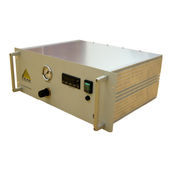
- Page 1 ZERO AIR GAS GENERATOR USER MANUAL UM- Zero Air 19”Rack System...
-
Page 2: Table Of Contents
ZA-070-19”Rack System Gas Generator UM – ZA-070 Contents Contents Page No Document History Warranty Statement Safety Notice to Users Safety Notice Declaration of Conformity Introduction and unpacking Electrical & Air Connection Principle of Operation Commissioning Maintenance Schedule Technical Specifications Pneumatic Diagram Electrical Diagram Maintenance Log Notes... -
Page 3: Document History
ZA-070-19”Rack System Gas Generator UM – ZA-070 History Rev. No. Changed Initials Date Document Created 12/01/02 Digital PID Controller fitted 25//01/02 USA Technical support number updated 16/11/04 New style front added 30/03/05 Technical Support number updated 10/11/04 Weight of unit changed to 13kg AMcB 02/06/05 Document Created on New Format... -
Page 4: Warranty Statement
SAFETY NOTICE TO USERS These instructions must be read thoroughly and understood before installation and operation of your Peak Scientific Zero Air. Use of the Generator in a manner not specified by Peak Scientific MAY impair the SAFETY provided by the equipment. -
Page 5: Safety Notice
UM – ZA-070 Safety Notice Safety First It is important that you thoroughly read and understand this manual before operating or servicing this Peak Scientific Instruments Gas Generator. PLEASE NOTE THE FOLLOWING CAUTIONS AND WARNINGS FOR YOUR OWN SAFETY. ! Caution –... -
Page 6: Declaration Of Conformity
ZA-070-19”Rack System Gas Generator UM – ZA-070 Declaration of Conformity Declaration of Conformity... -
Page 7: Introduction And Unpacking
UM – ZA-070 Introduction Introduction The Peak Scientific Instruments range of Zero Air Gas Generators is designed to produce a constant flow of Zero Grade Air with a Hydrocarbon content (as Methane) of less than 0.1 ppm. Unpacking and Installation Please save the product packaging for storage or future shipment of the generator. -
Page 8: Electrical & Air Connection
ZA-070-19”Rack System Gas Generator UM – ZA-070 CONNECTION Air Connection The Zero Air Generator should be connected to a clean, dry, OIL - FREE source of compressed air. A minimum pressure of 85 psig (5.86 barg ). The inlet and outlet connections are 1/4" BSP female. The Inlet air should conform to the following specifications: Minimum Pressure 85 psig... -
Page 9: Principle Of Operation
ZA-070-19”Rack System Gas Generator UM – ZA-070 Principle of Operation The ZA070-19R Zero Air generator works on the fundamental principle of Catalytic Oxidation as illustrated in the following pneumatic diagram. Heater Rod Thermocouple Cooling Inlet Filter / Coil Regulator Outlet Chamber ZAxxx Pneumatic Diagram Zero Air Generation... -
Page 10: Commissioning
ZA-070-19”Rack System Gas Generator UM – ZA-070 Commissioning This should be undertaken by a technically competent person. Prior to installing the generator into the Rack Cabinet, remove the lid. Check that all the internal components are securely located and have not moved during transit. Refit the lid. Open the air supply and switch the Power supply ON to unit. -
Page 11: Maintenance Schedule
ZA-070-19”Rack System Gas Generator UM – ZA-070 Maintenance Schedule WARNING: Servicing and/or repair of the Generator should only be undertaken by a TECHNICALLY COMPETENT PERSON with the Generator in a safely isolated condition. Routine Maintenance Due to the simplicity of design and the small number of parts the Peak Zero Air Generator will have a long and trouble free life. -
Page 12: Technical Specifications
ZA-070-19”Rack System Gas Generator UM – ZA-070 Technical Data General Details Minimum Operating Ambient Temperature C (41 Maximum Operating Ambient Conditions C (86 F) 70% RH(max) Inlet Conditions (Free of oil and bulk moisture) Minimum Air Inlet Pressure 85 psig (5.86 Barg) Maximum Air Inlet Pressure 125 psig (8.62 Barg) Minimum Air Inlet Flow Rate... -
Page 13: Pneumatic Diagram
ZA-070-19”Rack System Gas Generator UM – ZA-070 Pneumatic Pneumatic Diagram Heater Rod Thermocouple Cooling Inlet Filter / Coil Regulator Outlet Chamber ZAxxx Pneumatic Diagram... -
Page 14: Electrical Diagram
ZA015-070-19”Rack System Gas Generator ZA-070-19”Rack System Gas Generator UM – ZA015-070 UM – ZA-070 Electrical Diagram Electrical Diagram... -
Page 15: Maintenance Log
ZA-070-19”Rack System Gas Generator UM – ZA-070 Maintenance Log Maintenance log Model- Serial number Work Done Remarks Date Name... -
Page 16: Notes
ZA-070-19”Rack System Gas Generator UM – ZA-070 Notes...
Need help?
Do you have a question about the Zero Air ZA015 and is the answer not in the manual?
Questions and answers