Table of Contents
Advertisement
Quick Links
ISO 9001
IMPORTANT INSTRUCTIONS - SAVE THESE INSTRUCTIONS
Read all instructions before installing or using the heater. Please adhere to instructions published in this manual.
Failure to do so may be dangerous and may void certain provisions of your warranty.
Energy Management
System (EMS)
Installation & Operation Manual
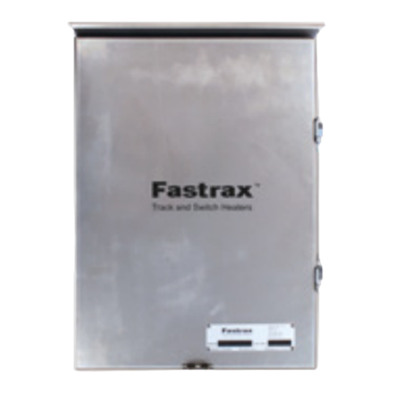
Control Box
ArcticSense
Rail Thermostat
Fastrax
is a registered trademark of Thermon.
®
Part No. HF17256.Rev.1
Issued December 2021 Printed in Canada
Copyright
2021. All rights reserved.
©
Advertisement
Table of Contents

Summary of Contents for Thermon Fastrax
- Page 1 Failure to do so may be dangerous and may void certain provisions of your warranty. Energy Management System (EMS) Installation & Operation Manual Control Box ArcticSense Rail Thermostat Fastrax is a registered trademark of Thermon. ® Part No. HF17256.Rev.1 Issued December 2021 Printed in Canada Copyright 2021. All rights reserved. ©...
-
Page 2: Table Of Contents
TABLE OF CONTENTS A. Energy Management System Overview A.1 Overview ................2 B. EMS Installation B.1 Mounting EMS Control Box ........3 B.2 Mounting Precipitation Sensor ......3 B.3 Mounting Rail Thermostat ........3 C. Electrical Connections Overview C.1 Power ..................5 C.2 ... -
Page 3: Ems Installation
EMS INSTALLATION B.1 Mounting EMS Control Box Mount the EMS control box in a convenient location on, or next to, the heater. B.2 Mounting Precipitation Sensor Mount the ArcticSense precipitation sensor on the Remove the four (4) Phillips screws, the cover, and sensor duct flange, where it will be exposed to snow the plug from the hole in the rail temperature surge and be in the heated zone. Slotted mounting holes facilitate attachment to the flange bolts in any of 2 position. Select the position that is most likely to be exposed to drifting snow. protection box. B.3 Mounting Rail Thermostat Mount the rail thermostat on the field or gage side ... - Page 4 Replace the cover, tighten the four (4) Phillips screws. Connect the surge isolator two pin connector with the mating plug located inside the electrical component area, hanging immediately under the DSI.
-
Page 5: Electrical Connections Overview
ELECTRICAL CONNECTIONS OVERVIEW Power & Simulate Set Point Dials Precipitation Switches Status LEDs CAUTION. Disconnect heater from power supply at On a Micro heater the signal is available at the integral disconnect or fuse box before opening “ALARM” relay terminal 9. closures or servicing heater. CAUTION NOTE: YARDMASTER heaters do not require this connection. Lock the switch in the “OFF” (open) position and The aggressive retry feature is integrated into the tag the switch to prevent unexpected power ... -
Page 6: Switches & Dials
C.6 Switches & Dials C.7 Status LEDs ‘POWER ON/OFF’ This allows you to turn OFF/ON the EMS. This switch Status LED Description is also used to reset the EMS in case of a lockout. Four Indicates 12V DC present on the alarms from the heater within less than 5 minutes. POWER board ‘SIMULATE PRECIPITATION ON/OFF’ Blinking once a second means clock This is normally OFF. To simulate moisture (snow or CLOCK is working rain) you can switch it ON and the EMS receives a signal the sensor is wet. Used to test and troubleshoot Heater relay is energized. Heaters HEATER ON the EMS. -
Page 7: Spare Parts & Drawings
SPARE PARTS & DRAWINGS EMS Board Part No. 15919 Circuit Breaker Part No. 9042-0014 Transformer Part No. 9064-0016 Metal Oxide Varistor Part No. 9049-0052 ArcticSense, c/w 10’ cable ArcticSense head only Rail thermostat c/w 40’ cable 13849-02 13849-03 16442-03 Rail thermostat surge Rail thermostat only, 13340- Rail thermostat jumper Ambient temperature sensor isolator. Replacement board 03 Enclosure only, 17895 16422-02 16426... -
Page 8: Schematic - Ems Board Single Unit
D.1 Schematic - EMS Board Single Unit... - Page 9 NOTES...
- Page 10 NOTES 10 10...
- Page 11 NOTES 11 11...
- Page 12 60 months - DC Heaters � 36 months - DC Control Panels � The Purchaser agrees that all warranty work required after the initial commissioning of the product will be provided 36 months - HELLFIRE Heaters, FEB Heaters � only if the Company has been paid by the Purchaser in full 12 months - All other Fastrax Products � ® accordance with the terms and conditions of the contract. Any claim for warranty must be reported to the sales offi ce where the product was purchased for authorized The Purchaser agrees that the Company makes no repair or replacement within the contract terms. warranty or guarantee, express, implied or statutory, ...


Need help?
Do you have a question about the Fastrax and is the answer not in the manual?
Questions and answers