Advertisement
Quick Links
Figure 2
Base Assembly
Figure 2
Top Asm.eps
Top Assembly
Flat Washer
and Hex Nut
1
4
/
" Hex Head Bolts
2
with Lock Washers
and Flat Washers
Left End Panel
Figure 4
1330 Bellevue Street • P .O. Box 8100 • Green Bay, WI 54308-8100 • Tel 1-800-424-2432 • www.ki.com
Figure 1
Left End Panel
Top
Assembly
2" Hex Head Bolts
with Lock Washers
and Flat Washers
Top Assembly
Left End Panel
Figure 3
2" Hex Head Bolts
with Lock Washers
and Flat Washers
Glides
© 2009 KI All Rights Reserved • Litho in USA. • Code KI-61562AR6-MBS/TMI/PDF/1109
Figure 4
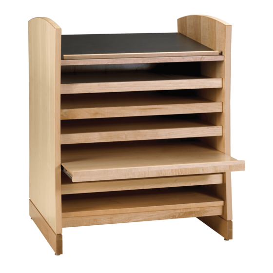
Assembly Instructions
CrossRoads
®
Single Face Metal with Back Stop
November 2009
Base Assembly
Left End Panel
2" Hex Head Bolts
with Lock Washers
and Flat Washers
Figure 1
2" Hex Head Bolts
with Lock Washers
and Flat Washers
Base Assembly.eps
Glides
Right End Panel
Rt. End Pnl Install.eps
Base Assembly
Shared End Panel
Figure 3
Assemble units as described herein only. To do otherwise
may result in instability. All screws, nuts and bolts must
be tightened securely and must be checked periodically
after assembly. Failure to assemble properly, or to secure
parts may result in assembly failure and injury.
Tools Required:
• #2 Phillips screwdriver
•
1
/
" socket
Shelving
2
• Socket wrench
Hardware Included:
• #8 x
• #8 x 1
•
5
/
16
•
5
/
16
•
/
" flat washer
1
4
•
5
/
16
•
5
/
16
•
5
/
16
• Metal pegs
1. Set back edge of left end panel on flat
surface (holes to inside – if it's a
curved end panel make sure the
curved edge is up).
2. Align the side holes in the base assembly
with the lower holes in the left end
panel. Insert 2" hex head bolts with
lock washers and flat washers into the
base and end panel. Tighten (Figure 1).
3. Align the side holes in the top
assembly with the upper holes in the
left end panel (Figure 2). Make sure
the faceplate on the top assembly is to
the front and that the back panel
groove is to the back. Insert 2" hex
head bolts with lock washers and flat
washers into the top assembly and
end panel. Tighten. Note: for shelving
units 72" and higher, the top shelf
Right End Panel
assembly should be flipped so that
the cleat side faces up.
4. For single starter unit (stand-alone)
and final end panel for connecting
units: Take the right end panel (holes
to inside) and align the side with the
holes in both the base and the top
assembly (Figure 3). Insert 2" hex
Base Assembly
head bolts with lock washers and flat
washers into the base and top
assembly. Tighten.
5. For adder units (connecting) – Align
the side holes in the shared panel
(holes both sides) with the holes in
both the base assembly and the top
assembly. Insert 4
with lock washers, flat washers and
nut into the base assembly. Do not
tighten (Figure 4).
6. Align the side holes in both the base
and top assembly with the side holes
in the right end panel. Insert 2" hex
head bolts with lock washers and flat
washers into base assembly and top
assembly (Figure 4).
7. Tighten all 2" and 4
Insert glides into all end panels.
5
/
" screws
8
1
/
" screws
4
" x 2" hex head bolt
" x 4
1
/
" hex head bolt
2
" lock washer
" flat washer
" hex nut
1
/
" hex head bolts
2
1
/
" hex head bolts.
2
Advertisement

Related Manuals for KI CrossRoads Shelving Single Face Metal with Back Stop


Summary of Contents for KI CrossRoads Shelving Single Face Metal with Back Stop
- Page 1 Insert glides into all end panels. parts may result in assembly failure and injury. 1330 Bellevue Street • P .O. Box 8100 • Green Bay, WI 54308-8100 • Tel 1-800-424-2432 • www.ki.com © 2009 KI All Rights Reserved • Litho in USA. • Code KI-61562AR6-MBS/TMI/PDF/1109...
- Page 2 CrossRoads ® Shelving - Single Face Metal with Back Stop Assembly Instructions Assemble units as described herein only. To do otherwise may result in instability. All screws, nuts and bolts must be tightened securely and must be checked periodically after assembly.
Need help?
Do you have a question about the CrossRoads Shelving Single Face Metal with Back Stop and is the answer not in the manual?
Questions and answers