
Subscribe to Our Youtube Channel
Related Manuals for Tyco Electronics 871087


Summary of Contents for Tyco Electronics 871087
- Page 1 Customer Manual Air Tools TERMI-POINT (diverse types) 871087 Customer Manual No.: 412-18008 _Rev. D1 Language: en (Translation of the original German version)
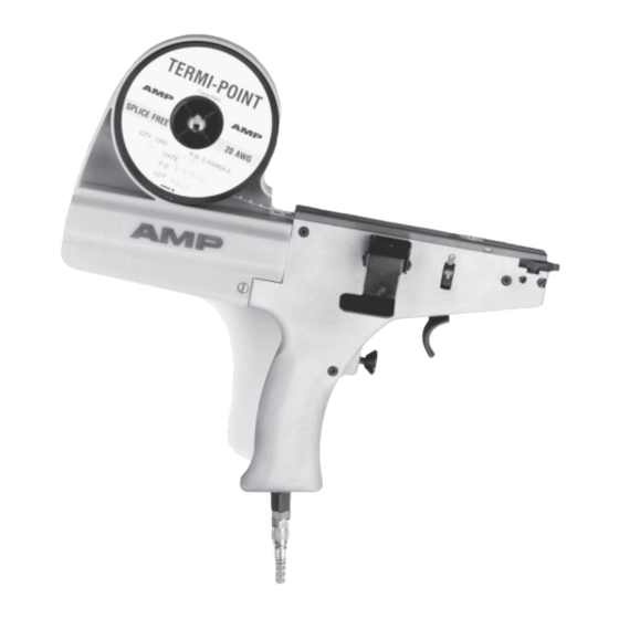
- Page 2 It must be remembered that our products are subject to a natural process of wear and aging ©2013 Tyco Electronics AMP GmbH, a TE Connectivity company. All rights reserved. The cover page shows a sample configuration. The delivered product may thus differ from the figure.
-
Page 3: Table Of Contents
Introduction ......................15 5.2.2 Per GP 1935 Rev. Germany 3/86 ................16 5.2.3 Per GP 1944 Rev. Germany 3/86 ................18 ©2013 Tyco Electronics AMP GmbH, a TE Connectivity company. Customer Manual 1/ 64 All rights reserved. 412-18008 Rev. D1 TE Connectivity, TE connectivity (logo), TERMI-POINT and Tyco Electronics are Trademarks. - Page 4 15.1.1 Air Tool TERMI-POINT 871087-1 ................42 15.1.2 Air Tool TERMI-POINT 871087-2 ................43 15.1.3 Air Tool TERMI-POINT 1-871087-1 (special model) ..........44 15.1.4 Air Tool TERMI-POINT 1-871087-2 (special model) ..........45 15.1.5 Air Tool TERMI-POINT 2-871087-1 (special model) ..........46 ©2013 Tyco Electronics AMP GmbH, a TE Connectivity company.
- Page 5 Air Tools TERMI-POINT (diverse types) 15.1.6 Air Tool TERMI-POINT 2-871087-2 (special model) ..........47 15.1.7 Air Tool TERMI-POINT 2-871087-3 (special model) ..........48 15.1.8 Air Tool TERMI-POINT 2-871087-4 (special model) ..........49 15.1.9 Air Tool TERMI-POINT 4-871087-1 (special model) ..........50 15.2...
-
Page 6: General Information
All rights, including rights created by patent grant or registration of a utility model or design, are reserved. Subject to change without notice. Errors and omissions excepted. ©2013 Tyco Electronics AMP GmbH, a TE Connectivity company. Customer Manual 4/ 64 All rights reserved. -
Page 7: Using The Operation Manual
Read these instructions completely, especially section 3 „General safety instructions”, before working with the Hand tool. Tyco Electronics AMP GmbH decline to accept any liability for damages that are incurred due to the fact that the instructions in the operation manual have been disregarded. -
Page 8: General Safety Instructions
5.2 „Tools, Mandrels and Clips“. Moreover, the hand tool may used exclusively within the limits of its intended use (section 3.1 „Intended use“). ©2013 Tyco Electronics AMP GmbH, a TE Connectivity company. Customer Manual 6/ 64 All rights reserved. -
Page 9: Qualification Of Personnel
If this information is disregarded, it may result in machine NOTE malfunction or breakdown. ©2013 Tyco Electronics AMP GmbH, a TE Connectivity company. Customer Manual 7/ 64 All rights reserved. 412-18008 Rev. D1 TE Connectivity, TE connectivity (logo), TERMI-POINT and Tyco Electronics are Trademarks. -
Page 10: Pictograms Used
Fig. 1 Wear proctective goggles (see / Pos. 2) These pictograms are placed on the Hand tool. Fig. 1: Pictograms ©2013 Tyco Electronics AMP GmbH, a TE Connectivity company. Customer Manual 8/ 64 All rights reserved. 412-18008 Rev. D1 TE Connectivity, TE connectivity (logo), TERMI-POINT and Tyco Electronics are Trademarks. -
Page 11: Adhere To The Following Instructions
Never cycle tool without having side and top cover securely installed. Before operating, make sure that compatible post, clip, wire and wire insulation are being used. ©2013 Tyco Electronics AMP GmbH, a TE Connectivity company. Customer Manual 9/ 64 All rights reserved. -
Page 12: During Maintenance And Repair
3.8.1 Obligations of the Operator The operator of the Tyco Electronics AMP GmbH products is bound to provide for personnel training on a regular basis regarding the following subjects: Observation and use of the operating instructions and the legal regulations. -
Page 13: Responsibility Of The Carrier
Risk of crushing due to insertion of the rod pushs Risk of cutting damage due to sharp edges at the housing of nippers ©2013 Tyco Electronics AMP GmbH, a TE Connectivity company. Customer Manual 11/ 64 All rights reserved. -
Page 14: Scope Of Delivery
(diverse types) Scope of delivery The scope of delivery includes following parts: 1 Air Tool TERMI-POINT (type as ordered) 1 operating manual ©2013 Tyco Electronics AMP GmbH, a TE Connectivity company. Customer Manual 12/ 64 All rights reserved. 412-18008 Rev. D1 TE Connectivity, TE connectivity (logo), TERMI-POINT and Tyco Electronics are Trademarks. -
Page 15: Product Description
0,8 x 1,6 x 22 3 max. 871087-2 0,8 x 2,4 x 26 3 max. 871087-1 ©2013 Tyco Electronics AMP GmbH, a TE Connectivity company. Customer Manual 13/ 64 All rights reserved. 412-18008 Rev. D1 TE Connectivity, TE connectivity (logo), TERMI-POINT and Tyco Electronics are Trademarks. -
Page 16: Identification Of Product
Manufacturing date (MM.YYYY) Work pressure [hPa] Part No. Product description CE - label ©2013 Tyco Electronics AMP GmbH, a TE Connectivity company. Customer Manual 14/ 64 All rights reserved. 412-18008 Rev. D1 TE Connectivity, TE connectivity (logo), TERMI-POINT and Tyco Electronics are Trademarks. -
Page 17: Tools, Mandrels And Clips
The clip (1) is identified by a colored dot or stripe on the crown of the clip (Fig. 5). Fig. 5: Codification Clip Mandrels and mandrel inserts (1) are color coded as shown in Fig. 6. Fig. 6: Codification mandrel ©2013 Tyco Electronics AMP GmbH, a TE Connectivity company. Customer Manual 15/ 64 All rights reserved. -
Page 18: Per Gp 1935 Rev. Germany 3/86
Pneumatic Tool Part. Pneumatic Tool Part. Pneumatic Tool Part. Pneumatic Tool Part.- - - - No. No. 871087 871087 871087- - - - 2 2 2 2 871087 Wire Size Mandreal Clips (1000/Reel) Finish Mandrel and Clip Insulation -ø... - Page 19 0.20 1.17 – 1.65 69561-4 3-330854-0 Pneumatic Tool Part. Pneumatic Tool Part.- - - - No. No. 871087 871087- - - - 1 1 1 1 Pneumatic Tool Part. Pneumatic Tool Part. 871087 871087 Wire Size Mandreal Clips (250/Reel) Finish Mandrel and Clip Insulation -ø...
-
Page 20: Per Gp 1944 Rev. Germany 3/86
Abisoliereinsatz und massiv oder Litze (7adr.) Clip [mm²] 0,56 yellow 0,20 ©2013 Tyco Electronics AMP GmbH, a TE Connectivity company. Customer Manual 18/ 64 All rights reserved. 412-18008 Rev. D1 TE Connectivity, TE connectivity (logo), TERMI-POINT and Tyco Electronics are Trademarks. -
Page 21: Commissioning
Install the hoses so, that they are no risk! Risk Of Injury! Risk of eye injuries due to the clips, which were shooted out! Wear protective goggles. ©2013 Tyco Electronics AMP GmbH, a TE Connectivity company. Customer Manual 19/ 64 All rights reserved. -
Page 22: Tool Preparation
With clips loaded (Fig. 8) and mandrel installed Fig. 7), connect tool to air supply and regard all applications in section 3 „General safety instructions“. Fig. 8: Clip Level ©2013 Tyco Electronics AMP GmbH, a TE Connectivity company. Customer Manual 20/ 64 All rights reserved. - Page 23 Practice to achieve smooth trigger control and to overcome tendency to flinch. Note that termination cycle is completed each time trigger is squeezed Refer to section 9.1 „Clip Positioning Adjustment“ for clip positioning. ©2013 Tyco Electronics AMP GmbH, a TE Connectivity company. Customer Manual 21/ 64 All rights reserved.
-
Page 24: Loading The Tool
(no clip present in push rod) repeat steps 4 trough 6, make sure that rear catch “clicks” into position behind the first clip. ©2013 Tyco Electronics AMP GmbH, a TE Connectivity company. Customer Manual 22/ 64 All rights reserved. -
Page 25: Unloading The Tool
NOTE damage cutting edge of mandrel! Release post pickups and insert mandrel holding shoulder screw, do not tighten it. Fix screw (10). ©2013 Tyco Electronics AMP GmbH, a TE Connectivity company. Customer Manual 23/ 64 All rights reserved. 412-18008 Rev. D1 TE Connectivity, TE connectivity (logo), TERMI-POINT and Tyco Electronics are Trademarks. -
Page 26: Transport And Storage
Protect the tool from knocks or stresses; Protect the tool from high levels of humidity and from big temperature changes; Prevent the tool from coming into contact with corrosive substances. ©2013 Tyco Electronics AMP GmbH, a TE Connectivity company. Customer Manual 24/ 64 All rights reserved. -
Page 27: Operation
Insert end of wire (unstripped) through wire funnel into opening between clip guide anvil and mandrel until wire bottoms. Release lever (3); wire is clamped in place. Fig. 11: Alignment of Mandrel Tool ©2013 Tyco Electronics AMP GmbH, a TE Connectivity company. Customer Manual 25/ 64 All rights reserved. - Page 28 Full lenght of clip curls must grip post Distance 10 Correct 11 Clips must not override 12 Last clip on post ©2013 Tyco Electronics AMP GmbH, a TE Connectivity company. Customer Manual 26/ 64 All rights reserved. 412-18008 Rev. D1 TE Connectivity, TE connectivity (logo), TERMI-POINT and Tyco Electronics are Trademarks.
- Page 29 Wire insulation strippings are collected in container of tool NOTE and should be removed periodically (Fig. 13). Fig. 13: Removal of Container ©2013 Tyco Electronics AMP GmbH, a TE Connectivity company. Customer Manual 27/ 64 All rights reserved. 412-18008 Rev. D1 TE Connectivity, TE connectivity (logo), TERMI-POINT and Tyco Electronics are Trademarks.
-
Page 30: Adjustment
Having selected setting 1, the clip is positioned on the upper, using setting 3 on the lower level of the post (Fig. 8). Fig. 14: Clip Positioning Adjustment Type 4-871087-1 (spezial model) includes a reduced slide-on measure of NOTE 7.4 mm! Ensure that positioner dial is properly positioned before squeezing trigger. -
Page 31: Maintenance And Repair
Minor repairs, adjustments and parts replacement instructions are provided in section 13 „Repairing / Replacement of Wear Parts“. For major repairs, replacement, and factory service contact customer service at Tyco Electronics AMP GmbH. ©2013 Tyco Electronics AMP GmbH, a TE Connectivity company. Customer Manual 29/ 64 All rights reserved. -
Page 32: Tool Check (Weekly)
Ensure that passageway for insulation strippings is clear. Check mandrel and clip guide anvil for burrs or nicks (Fig. 17). Fig. 17: Mandrel & Clip Guide Anvil Check ©2013 Tyco Electronics AMP GmbH, a TE Connectivity company. Customer Manual 30/ 64 All rights reserved. -
Page 33: Disposal
Careless disposal of the applicator lead to pollution of the environment. In case of disposal, please send the hand tool back to the address specified in section 15.6 „Address After Sales Serviced“. ©2013 Tyco Electronics AMP GmbH, a TE Connectivity company. Customer Manual 31/ 64 All rights reserved. -
Page 34: Troubleshooting
Assembly drawings and parts list are included for parts identification (ref. section 15.1 „List of spare parts“). Replacement and spare parts can be purchased from Tyco Electronics AMP GmbH. If problems occur that cannot be corrected with the aid of the troubleshooting chart, please contact customer service at Tyco Electronics AMP GmbH (section 15.6 „Address After Sales Serviced“). - Page 35 Worn or broken front catch Replace front catch (section 14.4) Fatigued or broken front catch spring Replace spring (section 14.4) Table 1: Troubleshooting chart ©2013 Tyco Electronics AMP GmbH, a TE Connectivity company. Customer Manual 33/ 64 All rights reserved. 412-18008 Rev. D1 TE Connectivity, TE connectivity (logo), TERMI-POINT and Tyco Electronics are Trademarks.
-
Page 36: Repairing / Replacement Of Wear Parts
(diverse types) Repairing / Replacement of Wear Parts All replacement processes refers to assembly drawing Fig. 18. Fig. 18: Assembly Drawing ©2013 Tyco Electronics AMP GmbH, a TE Connectivity company. Customer Manual 34/ 64 All rights reserved. 412-18008 Rev. D1 TE Connectivity, TE connectivity (logo), TERMI-POINT and Tyco Electronics are Trademarks. -
Page 37: Push Rod And Saddle Spring Replacement
Fig. 19: Clip Guide Anvil Replacement Block Screw (item 7) Rear of clip guide anvil 4 Screw (item 8) ©2013 Tyco Electronics AMP GmbH, a TE Connectivity company. Customer Manual 35/ 64 All rights reserved. 412-18008 Rev. D1 TE Connectivity, TE connectivity (logo), TERMI-POINT and Tyco Electronics are Trademarks. -
Page 38: Post Pickups Replacement
Lift left post pickup from its pin; use care not to lose spring. Replace each post pickup (25; 26) and perform steps 4 thru 1 in reverse order; carefully dress the tubing in its space. ©2013 Tyco Electronics AMP GmbH, a TE Connectivity company. Customer Manual 36/ 64 All rights reserved. -
Page 39: Front / Rear Catch And Spring Replacement
12. Replace push rod and compression spring (39), tighten cover (3) by 4 screws and replace side cover. Take care that compression spring (39) is placed correctly. ©2013 Tyco Electronics AMP GmbH, a TE Connectivity company. Customer Manual 37/ 64 All rights reserved. -
Page 40: Air Cylinder Replacement
Carefully screw replacement air cylinder into the tool by simultaneously pulling and screwing until air cylinder reaches its end-position. Check that dimension “9.4 mm” is ok (Fig. 21)! Fig. 21: Dimension check Type 4-871087-1 (spezial model) includes a reduced slide-on measure of NOTE 7.4 mm! Perform steps 6 thru 2 in reverse order. -
Page 41: Replacement Of Miniature Valve / Actuator
The position of recommended equipment is shown in Fig. 22. If air pressure exceeds 6.5 bar an air regulator should be installed. Fig. 22: Air Filter ©2013 Tyco Electronics AMP GmbH, a TE Connectivity company. Customer Manual 39/ 64 All rights reserved. -
Page 42: Technical Data
5.5 bar (min.) to 6.5 bar (max.) Tool Weight: approx. 1 kg incl. mandrel, fully loadedreel and air line Air Volume Required: 5 cu. per cycle ©2013 Tyco Electronics AMP GmbH, a TE Connectivity company. Customer Manual 40/ 64 All rights reserved. 412-18008 Rev. D1 TE Connectivity, TE connectivity (logo), TERMI-POINT and Tyco Electronics are Trademarks. -
Page 43: Appendix
(diverse types) Appendix 15.1 List of spare parts Fig. 23: List of Spare parts ©2013 Tyco Electronics AMP GmbH, a TE Connectivity company. Customer Manual 41/ 64 All rights reserved. 412-18008 Rev. D1 TE Connectivity, TE connectivity (logo), TERMI-POINT and Tyco Electronics are Trademarks. -
Page 44: Air Tool Termi-Point 871087-1
871330-1 Wire cutter 871331-1 Balance holder [*sold separately / not part of toolin equipment] ©2013 Tyco Electronics AMP GmbH, a TE Connectivity company. Customer Manual 42/ 64 All rights reserved. 412-18008 Rev. D1 TE Connectivity, TE connectivity (logo), TERMI-POINT and Tyco Electronics are Trademarks. -
Page 45: Air Tool Termi-Point 871087-2
871295-5 Stripper insert AWG 26 871330-1 Wire cutter 871331-1 Balance holder ©2013 Tyco Electronics AMP GmbH, a TE Connectivity company. Customer Manual 43/ 64 All rights reserved. 412-18008 Rev. D1 TE Connectivity, TE connectivity (logo), TERMI-POINT and Tyco Electronics are Trademarks. -
Page 46: Air Tool Termi-Point 1-871087-1 (Special Model)
(diverse types) 15.1.3 Air Tool TERMI-POINT 1-871087-1 (special model) This type of tool applies for pin layouts 90° turne d. The following table only shows parts differing from the standard version 871087-1 (page 42). Fig. 24: Special Model Item Part No. -
Page 47: Air Tool Termi-Point 1-871087-2 (Special Model)
(diverse types) 15.1.4 Air Tool TERMI-POINT 1-871087-2 (special model) This type of tool applies for pin layouts 90° turne d. The following table only shows parts differing from the standard version 871087-1 (page 42). Fig. 25: Special Model Item Part No. -
Page 48: Air Tool Termi-Point 2-871087-1 (Special Model)
871295-2 Stripper insert AWG 24 871330-1 Wire cutter 871331-1 Balance holder ©2013 Tyco Electronics AMP GmbH, a TE Connectivity company. Customer Manual 46/ 64 All rights reserved. 412-18008 Rev. D1 TE Connectivity, TE connectivity (logo), TERMI-POINT and Tyco Electronics are Trademarks. -
Page 49: Air Tool Termi-Point 2-871087-2 (Special Model)
871295-3 Stripper insert AWG 22 871330-1 Wire cutter 871331-1 Balance holder ©2013 Tyco Electronics AMP GmbH, a TE Connectivity company. Customer Manual 47/ 64 All rights reserved. 412-18008 Rev. D1 TE Connectivity, TE connectivity (logo), TERMI-POINT and Tyco Electronics are Trademarks. -
Page 50: Air Tool Termi-Point 2-871087-3 (Special Model)
871337-1 Reduction 871295-7 Stripper insert AWG 22 871330-1 Wire cutter ©2013 Tyco Electronics AMP GmbH, a TE Connectivity company. Customer Manual 48/ 64 All rights reserved. 412-18008 Rev. D1 TE Connectivity, TE connectivity (logo), TERMI-POINT and Tyco Electronics are Trademarks. -
Page 51: Air Tool Termi-Point 2-871087-4 (Special Model)
519056-4 Tightening Pin 871328-3 657728-9 O-ring 871337-1 Reduction ©2013 Tyco Electronics AMP GmbH, a TE Connectivity company. Customer Manual 49/ 64 All rights reserved. 412-18008 Rev. D1 TE Connectivity, TE connectivity (logo), TERMI-POINT and Tyco Electronics are Trademarks. * Other products, logos and company names mentioned herein may be trademarks of their respective owners... -
Page 52: Air Tool Termi-Point 4-871087-1 (Special Model)
Because the tool is not mechanically secured against improper tool justification, the user has to take care for the correct justification. Tool 4-871087-1 is exclusively authorized for using Weidmüller clips SAK T / TT 0.8x2.4 + KMVT RE 2.4 EP/SW only and therefore the use of other clips than decribed above is not allowed. - Page 53 Air Tools TERMI-POINT (diverse types) Fig. 27: Special Model ©2013 Tyco Electronics AMP GmbH, a TE Connectivity company. Customer Manual 51/ 64 All rights reserved. 412-18008 Rev. D1 TE Connectivity, TE connectivity (logo), TERMI-POINT and Tyco Electronics are Trademarks. * Other products, logos and company names mentioned herein may be trademarks of their respective owners...
- Page 54 871330-1 Wire cutter 871331-1 Balance holder [*sold separately / not part of toolin equipment] ©2013 Tyco Electronics AMP GmbH, a TE Connectivity company. Customer Manual 52/ 64 All rights reserved. 412-18008 Rev. D1 TE Connectivity, TE connectivity (logo), TERMI-POINT and Tyco Electronics are Trademarks.
-
Page 55: Operator's Quality Check Procedure
NOTE The following recommended procedure is intended as a guide in establishing quality control criteria for TERMI-POINT clip when applied to Tyco Electronics AMP GmbH posts with TERMI-POINT tooling. Individual requirements will dictate the extent of the quality control program. - Page 56 11-0 16 - 25 15.2.1.2 Production Test The following procedure is recommended by Tyco Electronics AMP GmbH to assure a satisfactory level of quality for TERMI-POINT clip applications: Visual Examination Each operator should make a visual inspection of all terminations per Publication GP 2019, item numbers 1 thru 3.
-
Page 57: Pull Test Tool Part-No. 69358-2
Test tip Top of tool engages ends of curls on clip Post Indicator ring ©2013 Tyco Electronics AMP GmbH, a TE Connectivity company. Customer Manual 55/ 64 All rights reserved. 412-18008 Rev. D1 TE Connectivity, TE connectivity (logo), TERMI-POINT and Tyco Electronics are Trademarks. - Page 58 (applies to 15.3.1.1. too) NOTE Clips that move more than 1/2 of the clip length should be rejected, test should be repeated with a new clip! ©2013 Tyco Electronics AMP GmbH, a TE Connectivity company. Customer Manual 56/ 64 All rights reserved.
- Page 59 Pull tool while using a rate of 0,5 inches per second. Gradually decrease pull rate until indicator ring is in line with front of tool. Check gage reading. If gage reading is not satisfactory, test tool should be returned to Tyco Electronics AMP GmbH.
-
Page 60: Operators's Quality Check Procedure For Termi-Point
Refer to publication GP 1920 for additional information. 15.4.2 Clip Application Post Size: 0.8 mm x 1.6 mm and 0.8 mm x 2.4 mm ©2013 Tyco Electronics AMP GmbH, a TE Connectivity company. Customer Manual 58/ 64 All rights reserved. 412-18008 Rev. D1 TE Connectivity, TE connectivity (logo), TERMI-POINT and Tyco Electronics are Trademarks. - Page 61 Insulation silvers permitted Metal to metal-contact between Full length of clip curls must wire and post grip post ©2013 Tyco Electronics AMP GmbH, a TE Connectivity company. Customer Manual 59/ 64 All rights reserved. 412-18008 Rev. D1 TE Connectivity, TE connectivity (logo), TERMI-POINT and Tyco Electronics are Trademarks.
- Page 62 Back end of clip Clips may seat on each other Clearance equal to or greater than insulation diameter Clips must not override ©2013 Tyco Electronics AMP GmbH, a TE Connectivity company. Customer Manual 60/ 64 All rights reserved. 412-18008 Rev. D1 TE Connectivity, TE connectivity (logo), TERMI-POINT and Tyco Electronics are Trademarks.
- Page 63 Clips that move more than 1/2 clip length during test should be rejected, a new clip applied, and the pull test repeated. ©2013 Tyco Electronics AMP GmbH, a TE Connectivity company. Customer Manual 61/ 64 All rights reserved.
-
Page 64: Extraction Tool Part No. 69357-3
Tip of extraction tool Post Twist tool in clockwise direction away from open portion of TERMI-POINT clip until clip is free (Fig. 36). ©2013 Tyco Electronics AMP GmbH, a TE Connectivity company. Customer Manual 62/ 64 All rights reserved. 412-18008 Rev. D1 TE Connectivity, TE connectivity (logo), TERMI-POINT and Tyco Electronics are Trademarks. -
Page 65: Clip Positioning Procedure
To insure contact reliability, this tool should not be used to push more than one clip at a time. Carefully push clip to desired position on post. Fig. 37: Clip Positioning Procedure ©2013 Tyco Electronics AMP GmbH, a TE Connectivity company. Customer Manual 63/ 64 All rights reserved. -
Page 66: Address After Sales Serviced
Air Tools TERMI-POINT (diverse types) 15.6 Address After Sales Serviced Tyco Electronics AMP GmbH a TE Connectivity Ltd. company Schenck Technologie- und Industriepark Landwehrstr. 55 / Gebäude 83 D-64293 Darmstadt Field Service EMEA@te.com TE AT Kundendienst-Hotline: +49-6151-607-1518 ©2013 Tyco Electronics AMP GmbH, a TE Connectivity company.
Need help?
Do you have a question about the 871087 and is the answer not in the manual?
Questions and answers