Table of Contents
Advertisement
Quick Links
PROPER USE GUIDELINES
Cumulative Trauma Disorders can result from the prolonged use of manually powered hand tools. Hand tools are intended for occasional use and low volume
applications. A wide selection of powered application equipment for extended-use, production operations is available.
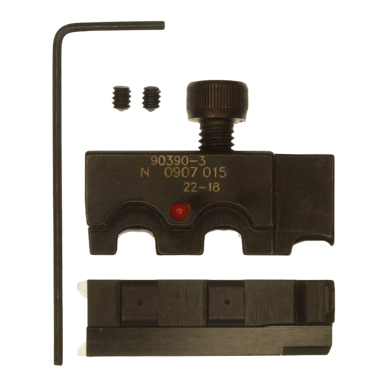
Crimp Symbol
(Dot Code)
Lower Die
Assembly
(Anvil)
Figure 1
1. INTRODUCTION
Platform Crimping Die Assemblies 90390–3 and
90391–3 are used in Platform Hand Tool Frame
58078–3 (408–6976). The die assemblies crimp the
Ultra–Fast Fully Insulated FASTON* Terminals listed
in Figure 2. Read These instructions before using the
Platform Hand Tool Frame and Platform Crimping
Dies.
Dimensions are in millimeters [with inch
NOTE
equivalents in brackets]. Figures are for
identification only and are not drawn to scale.
Reasons for reissue are provided in Section 7,
2. DESCRIPTION
Each die assembly consists of an upper die (crimper)
and a lower die (anvil), a retaining screw (on the
upper die), and a hex wrench for securing the lower
die to the platform of the hand tool frame.
The die assemblies are identified by part
numbers,color dot codes, and applicable wire range
designations. See Figure 1. The 90390–3 die
assembly has a red color dot on both the crimper and
the anvil, while the 90391–3 die assembly has a blue
color dot on the crimper and the anvil. The color
E
2006 Tyco Electronics Corporation, Harrisburg, PA
All International Rights Reserved
Tyco is a trademark.
*Trademark
Other products, logos, and company names used are the property of their respective owners.
Crimping Die Assemblies
90390-3 and 90391-3
coding on the die assembly corresponds to the color
coding on translucent insulation of the Ultra–Fast
Die Retaining
FASTON terminal for easier identification when
Screw
crimping.
Upper Die
Assembly
3. INSTALLATION
(Crimper)
Determine the part number of the terminal you are
crimping, then refer to the table in Figure 2 and select
the appropriate die assembly. Install dies as
described below.
3.1. Installing Lower Die Assembly
1. Squeeze the tool handlers together until they
Color
bottom. Then allow them to open fully.
Code
2. Hold the hand tool frame so that the back of the
tool is facing you and note the socket head screw
located in the lower die platform. See Figure 3.
3. Slide the lower die onto the lower platform,
ensuring that the drilled holes on the side of the
lower die line up with the socket head screw.
NOTE
4. With the lower die in place, turn the socket head
screw (on the die platform) clockwise until snug.
Do NOT overtighten.
3.2. Installing Upper Die Assembly
1. Remove the die retaining screw from the die
assembly.
2. Position the upper die in upper die platform of
the tool. Thread the die retaining screw through the
mounting hole in the top of tool and tighten the
screw until it is snug but NOT secured.
3. While guiding the upper die into alignment with
the lower die, slowly close the tool handles until the
dies bottom.
4. Tighten the upper die retaining screw until the
die is secure.
5. Squeeze the tool handles together until the
ratchet releases. Allow the tool handles to open
fully. The tool is now ready for use.
TOOLING ASSISTANCE CENTER 1-800-722-1111
PRODUCT INFORMATION 1-800-522-6752
Instruction Sheet
408-9279
25 JUL 06
If the lower die will not seat on the lower die
platform with the drilled hole aligned with the
socket head screw, use the hex wrench to turn
the screw either in or out until the set screw does
not protrude from either side of the lower tool jaw.
This controlled document is subject to change.
For latest revision and Regional Customer Service,
www.tycoelectronics.com
visit our website at
Rev B
1
of 5
LOC B
Advertisement
Table of Contents

Related Manuals for Tyco Electronics 90390-3


Summary of Contents for Tyco Electronics 90390-3
- Page 1 The color fully. The tool is now ready for use. TOOLING ASSISTANCE CENTER 1-800-722-1111 This controlled document is subject to change. 2006 Tyco Electronics Corporation, Harrisburg, PA of 5 PRODUCT INFORMATION 1-800-522-6752 For latest revision and Regional Customer Service, All International Rights Reserved www.tycoelectronics.com...
- Page 2 408-9279 Crimping Die Assemblies 90390-3 and 90391-3 Translucent Wire Barrel Wire Size and Insulation (Typ) Series Number 7.14 [.281] In-Line In-Line Tab Receptacle Wire Strip Flag Receptacle Terminal Terminal Length (Typ) Terminal WIRE TERMINAL WIRE SIZE INSUL DIA SERIES TYPE...
- Page 3 408-9279 Crimping Die Assemblies 90390-3 and 90391-3 S For flag terminals, the flat side of the wire end Die Retaining Upper Die must face outward and the mating end must Screw seat on the locator. 7. Squeeze the tool handles sufficiently to hold the terminal firmly in place without deforming it.
- Page 4 408-9279 Crimping Die Assemblies 90390-3 and 90391-3 If the crimping chamber conforms to the gage 5.2. Periodic Inspection inspection, the dies are considered dimensionally correct and should be lubricated with a THIN coat of Regular inspection should be performed by quality SAE 20 motor oil.
- Page 5 408-9279 Crimping Die Assemblies 90390-3 and 90391-3 6. REPLACEMENT AND REPAIR Dies may be returned to Tyco Electronics for evaluation and repair. For tool repair service, contact a Tyco Electronics Representative at The parts listed in Figure 6 are customer–...
Need help?
Do you have a question about the 90390-3 and is the answer not in the manual?
Questions and answers