Advertisement
Lockscrew
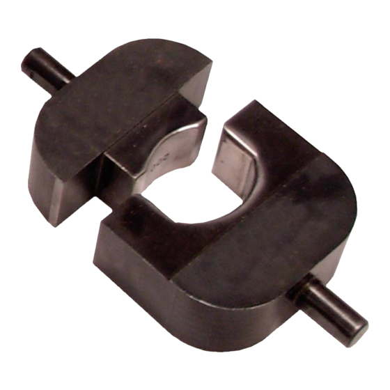
Ram Lockscrew
Figure 1
1. INTRODUCTION
AMPOWER Crimping Die Assemblies 68361-1,
68253-1, 68304-1, and 59867-1 (shown in Figure 1)
are designed for use in DYNA-CRIMP Crimping Head
69099, which is hydraulically activated by Hydraulic
Power Unit 69120-[ ] or Hydraulic Hand Pump
314979-1. Each die assembly, when installed in the
crimping head, will crimp AMPOWER Quick-
Disconnect Terminals onto standard wire sizes as
listed in Figure 2. Read these instructions thoroughly
before using the dies.
These instructions provide specific information
regarding the die assemblies and applicable terminals.
For information regarding die insertion/removal and
general operation of the DYNA-CRIMP Crimping
Head, refer to instruction sheet 408-2458. For
information on the Hydraulic Power Unit, refer to
customer manual 409-1950 and for information on the
Hydraulic Hand Pump, refer to 409-5860.
Reasons for reissue are provided in Section 6,
REVISION SUMMARY.
Dimensions in this instruction sheet are in metric
NOTE
units [with U.S. customary units in brackets].
Figures are not drawn to scale.
i
©2011 Tyco Electronics Corporation, Berwyn, PA
All Rights Reserved
TE logo and Tyco Electronics are trademarks.
*Trademark. Other products, logos, and company names might be trademarks of their respective owners.
AMPOWER* Crimping Die Assemblies
68361-1, 68253-1, 68304-1, and 59867-1
DYNA-CRIMP*
Crimping Head 69099
Flat on
Shank
Stationary
Die
Locator
Assembly
Moving Die
TOOLING ASSISTANCE CENTER 1-800-722-1111
PRODUCT INFORMATION 1-800-522-6752
2. DESCRIPTION
Each die assembly features a stationary die, a moving
die, and a locator assembly (refer to Figure 1). Both
the stationary and moving die have a shank (with a
flat) which is used to align and secure each die in the
crimping head. The locator assembly is used to aid in
positioning the terminal in the stationary die.
3. CRIMPING PROCEDURE
Install the dies according to the instructions contained
in 408-2458. Refer to the table in Figure 2 and select
the appropriate terminal and wire. Ensure that wire
size stamped on terminal corresponds with wire size
stamped on dies. Strip the wire to the length indicated.
Do NOT cut or nick the wire strands.
Refer to Figure 3 and proceed as follows:
To avoid personal injury when operating power unit,
DANGER
exercise caution when holding terminals or wires
near crimping area.
STOP
1. Position terminal in stationary die so that large,
flat surface of terminal is parallel to and resting
against angular surface of locator.
2. Hold the terminal in position and activate power
unit so that moving die advances just enough to
hold terminal in place. Do not deform terminal wire
barrel.
Terminal
WIRE
STRIP LENGTH
SIZE
MIN.
MAX.
1/0
29.46
30.99
2/0
[1.16]
[1.22]
3/0
4/0
Figure 2
This controlled document is subject to change.
For latest revision and Regional Customer Service,
visit our website at www.tycoelectronics.com
Instruction Sheet
408-2710
18 Mar 11 Rev G
Wire Strip
Length
DIE
TERMINAL
SET
NUMBER
NUMBER
52594-1, 52594-3,
68361-1
and 52594-3
52595-1
68253-1
52596-1
59867-1
53631-1
68304-1
1 of 5
LOC B
Advertisement
Table of Contents

Related Manuals for TE Connectivity AMPOWER 68361-1


Summary of Contents for TE Connectivity AMPOWER 68361-1
- Page 1 Instruction Sheet 408-2710 AMPOWER* Crimping Die Assemblies 68361-1, 68253-1, 68304-1, and 59867-1 18 Mar 11 Rev G 2. DESCRIPTION DYNA-CRIMP* Crimping Head 69099 Lockscrew Each die assembly features a stationary die, a moving die, and a locator assembly (refer to Figure 1). Both the stationary and moving die have a shank (with a Flat on flat) which is used to align and secure each die in the...
-
Page 2: Maintenance And Inspection Procedure
408-2710 4.1. Daily Maintenance 1. Remove dust, moisture, and other contaminants Flat Surface of with a clean brush, or a soft, lint-free cloth. Do NOT Terminal Rests use objects that could damage the dies. Against Locator 2. All surfaces should be protected with a thin coat of any good SAE 20 motor oil. - Page 3 408-2710 ACCEPT REJECT Slot Spread Open 2.00 [.079] Min. Dimension “A” Slots that are open too Vertical far may be closed by Centerline squeezing in vise. Large Slot 45° Vertical Centerline Wrong Crimp 6.35 / 6.48 Orientation [.250 / .255] Slot Spreads Open Crimped too far off center causing large slot Crimp located on wire barrel as shown.
-
Page 4: Revision Summary
408-2710 Suggested Plug Gage Design Dies Positioned At “Gage Dimension” GO Dia. NO-GO Dia. Wire Barrel Crimping Chamber Gage Dim. 42.27 [1.664] GO Element NO-GO Element Figure 6 GAGE DIMENSION CRIMPING DIE NUMBER GO (DIA) NO-GO (DIA) 6. REVISION SUMMARY 7.544 - 7.551 7.795 - 7.798 Since the last revision of this document, the following... -
Page 5: Part Description
408-2710 Dim. “A” Dim. “C” Dim. “B” Weight Approximately 794 g [1 lb 12 oz] DIE SET NUMBERS AND COMPONENT PART NUMBERS ITEM QTY PER PART DESCRIPTION NUMBER ASSY 68253-1 68304-1 68361-1 59867-1 2-21000-7 2-21000-7 2-21000-7 2-21000-7 SCREW, Skt Hd Cap, 8-32 x .500 L 308266-1 308266-1 308266-1... - Page 6 Punches & Dies Click to view products by manufacturer: TE Connectivity Other Similar products are found below : 58510-1 63454-1601 63456-0054 63457-3401 64000-0077 64005-0175 730-5/8 734410 PV-670508-001 1322 1338 1338120-1 1338650-1 1389G6 DIE-R-BNCX-PY 1388G4 1388G6 1389G9 1490593-1 1583609-1 1720 1762951-1 1901268-1 1901269-1 2063500-2 227-...
Need help?
Do you have a question about the AMPOWER 68361-1 and is the answer not in the manual?
Questions and answers