Advertisement
Quick Links
1. INTRODUCTION
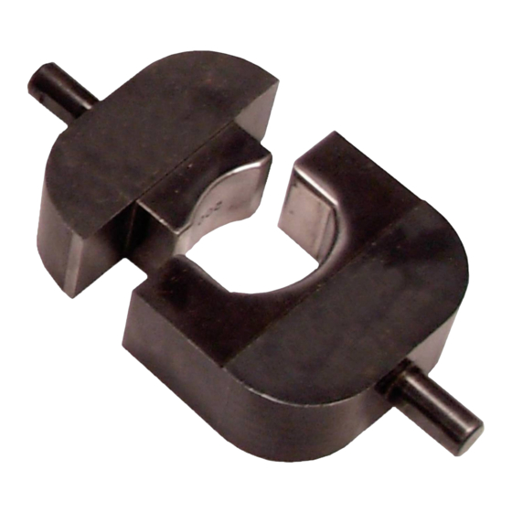
AMPOWER Crimping Die Assemblies 68361-1, 68253-1, 68304-1, and 59867-1 (shown in Figure 1) are
designed for use in DYNA-CRIMP™ Crimping Head 69099, which is hydraulically activated by Hydraulic Power
Unit 69120-[ ] or Hydraulic Hand Pump 314979-1.
Figure 1: AMPOWER Crimping Die Assemblies 68361-1, 68253-1, 68304-1, and 59867-1
1
2
3
4
© 2022 TE Connectivity Ltd. family of companies.
All Rights Reserved.
TE Connectivity, TE connectivity (logo), and TE (logo) are trademarks. Other logos, product, and/or company names may be trademarks of their respective owners.
AMPOWER™ Crimping Die Assemblies
68361-1, 68253-1, 68304-1, and 59867-1
Lock screw
Ram lock screw
DYNA-CRIMP crimping head 69099
Flat on shank
PRODUCT INFORMATION 1-800-522-6752
Stationary die
5
Locator assembly
6
Moving die
7
This controlled document is subject to change.
For latest revision and Regional Customer Service,
visit our website at www.te.com.
Instruction Sheet
408-2710
18 NOV 2022 Rev H
1 of 10
Advertisement

Subscribe to Our Youtube Channel
Related Manuals for TE Connectivity AMPOWER 68361-1


Summary of Contents for TE Connectivity AMPOWER 68361-1
- Page 1 1 of 10 For latest revision and Regional Customer Service, All Rights Reserved. visit our website at www.te.com. TE Connectivity, TE connectivity (logo), and TE (logo) are trademarks. Other logos, product, and/or company names may be trademarks of their respective owners.
- Page 2 408-2710 Table 1 lists the dimensions for each die set. The weight is approximately 794 g [1 lb 12 oz]. NOTE Dimensions in this instruction sheet are in millimeters with [inches in brackets]. Figures are for reference only and are not drawn to scale.
- Page 3 408-2710 2. DESCRIPTION Each die assembly features a stationary die, a moving die, and a locator assembly (see Figure 1). Both the stationary and moving die have a shank (with a flat), which aligns and secures each die in the crimping head. The locator assembly helps position the terminal in the stationary die.
- Page 4 408-2710 3. Insert the terminal into the stationary die. Orient it so that the large, flat surface of the terminal is parallel to, and rests against, the angular surface of the locator (Figure 4). Figure 4: Positioning the terminal Flat surface of terminal rests against locator Quick-disconnect pins must be on this side of locator Moving die 4.
- Page 5 408-2710 5. INSPECTING THE CRIMP Inspect crimped terminals by comparing to the ones shown in Figure 5 and Figure 6. Use only the terminals that display the features of an acceptable crimp (Figure 5). Figure 5: Features of an acceptable crimp Embossed wire size matches size stamped on terminal and CMA of wire.
- Page 6 408-2710 Figure 6 shows problems that mean a crimp should be rejected. Most of these are the caused by a terminal that is not properly aligned with the dies. Avoid unacceptable crimps by carefully following the procedures in section 4 and performing regular tool maintenance (section 6). As shown in Figure 6, the large slot in the terminal must meet the following requirements: ...
-
Page 7: Maintenance And Inspection
408-2710 6. MAINTENANCE AND INSPECTION The dies are inspected before being shipped. Inspect them immediately when they arrive at your facility to determine whether any damage occurred during shipment. 6.1. Daily maintenance Make each operator of the power unit aware of, and responsible for, the following daily maintenance requirements: ... - Page 8 408-2710 6.4. Gaging the crimping die closure This procedure requires the use of a plug gage (Figure 7) conforming to the dimensions listed in Table 6. TE Connectivity does not manufacture or market these gages. For information regarding the use of a plug gage, refer to instruction sheet 408-7424.
-
Page 9: Replacement And Repair
408-2710 To gage the die closure, complete the following steps. 1. Remove the dies from the crimping head. 2. Remove traces of oil or dirt from the crimping chambers and plug gage. 3. Position the dies at the gaging height shown in Figure 8. Figure 8: Gaging height 4. -
Page 10: Revision Summary
Shop TE link at the top of the page. Call 800-522-6752. Write to: CUSTOMER SERVICE (038-035) TE CONNECTIVITY CORPORATION PO BOX 3608 HARRISBURG PA 17105-3608 For customer repair services, call 800-522-6752. Figure 9: Replacement parts Table 7: Die set and component part numbers...
Need help?
Do you have a question about the AMPOWER 68361-1 and is the answer not in the manual?
Questions and answers