Advertisement
Quick Links
Advertisement

Subscribe to Our Youtube Channel
Related Manuals for Teknik Shaker Style 5428225


Summary of Contents for Teknik Shaker Style 5428225
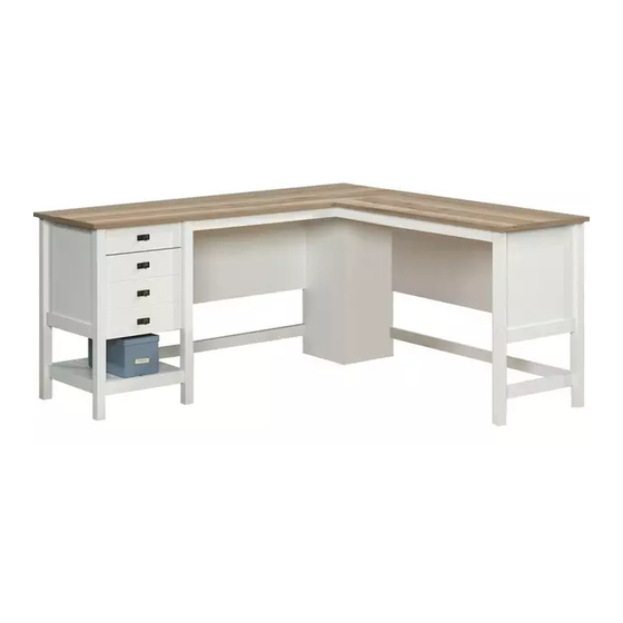
- Page 1 Teknik www.teknikoffice.co.uk Sit and surf. Shaker Style L-Shaped Desk Model 5428225...
- Page 2 Table of Contents Assembly Tools Required Part Identification No. 2 Phillips Screwdriver Hardware Identification Tip Shown Actual Size Hardware Usage Guide Assembly Steps 7-46 Hammer Not actual size Part Identification å While not all parts are labeled, some of the parts will have a label or an inked letter on the edge to help distinguish similar parts from each other.
- Page 3 Now you know Part Identification our ABCs. D716 D716 Page 3...
- Page 4 Hardware Identification å Screws are shown actual size. You may receive extra hardware with your unit. (EXTENSION SET SHOWN SEPARATED) EXTENSION RAIL - 4 EXTENSION SLIDE - 4 10A SLIDE CAM - 4 35MA 35MC FILE GLIDE - 2 FILE ROD - 2 HIDDEN CAM - 66 CAM DOWEL - 34 CAM SCREW - 32...
- Page 5 Hardware Identification å Screws are shown actual size. You may receive extra hardware with your unit. 3S GOLD 5/16" FLAT HEAD SCREW - 16 BLACK 9/16" LARGE HEAD SCREW - 14 30S BLACK 1-9/16" FLAT HEAD SCREW - 8 BLACK 9/16" FLAT HEAD SCREW - 4 113S BLACK 1-15/16"...
- Page 6 Hardware Usage Guide HOW TO USE A HIDDEN CAM & CAM DOWEL Insert the metal end of the CAM DOWEL into the HIDDEN CAM. Cam Dowel Arrow Hole Push a HIDDEN CAM into Metal end the part. The arrow in the HIDDEN CAM must point toward the hole in the edge Hidden Cam...
- Page 7 Step 1 å Assemble your unit on a carpeted floor or on the empty carton to avoid scratching your unit or the floor. å Push eight HIDDEN CAMS (1F) into the long edge of the SMALL MODESTY PANEL (O) and LEFT SUPPORT (CC). Then, insert the metal end of a CAM DOWEL (2F) into each HIDDEN CAM.
- Page 8 Step 2 å Fasten the LEFT SUPPORT (CC) to the SMALL MODESTY PANEL (O) and SMALL BRACE (W). Use four BLACK 1-15/16" FLAT HEAD SCREWS (113S). å NOTE: You should start each SCREW a few turns before completely tightening any of them. 113S BLACK 1-15/16"...
- Page 9 Step 3 å Push two HIDDEN CAMS (1F) into the short edge of the UPRIGHT (J). Then, insert the metal end of a CAM DOWEL (2F) into each HIDDEN CAM. å Now, push six HIDDEN CAMS (1F) into the UPRIGHT (J) and one SIDE SKIRT (T).
- Page 10 Step 4 å Turn twelve CAM SCREWS (8F) into the LEGS (M and N). å Insert six WOOD DOWELS (15F) into the LEGS (M and N). (12 used) Page 10...
- Page 11 Step 5 å Fasten the LEGS (M and N) to the UPRIGHT (J) and SIDE SKIRT (T). Tighten six HIDDEN CAMS. å NOTE: Be sure the WOOD DOWELS in the LEGS insert into the UPRIGHT. S u r f a c H I D Edge with D E N...
- Page 12 Step 6 å Separate the EXTENSION SLIDES (35MC) from the EXTENSION RAILS (35MA) as shown in the upper diagram below. Be prepared, the parts are greasy. å Fasten two EXTENSION RAILS (35MA) to the UPRIGHT (J). Use four GOLD 5/16" FLAT HEAD SCREWS (3S) through holes #1 and #3.
- Page 13 Step 7 å Fasten the CENTER REAR LEG (N) to the SMALL MODESTY PANEL (O). Tighten two HIDDEN CAMS. å NOTE: Be sure the WOOD DOWELS in the LEG insert into the MODESTY PANEL. å Fasten the CENTER REAR LEG (N) to the SMALL BRACE (W). Use two BLACK 1-15/16"...
- Page 14 Step 8 å Push two HIDDEN CAMS (1F) into the short edge of the BACK (E). Then, insert the metal end of a CAM DOWEL (2F) into each HIDDEN CAM. å Now, push four HIDDEN CAMS (1F) into the remaining holes in the BACK (E).
- Page 15 Step 9 å Fasten the BACK (E) to the CENTER REAR LEG (N). Tighten two HIDDEN CAMS. Edge with CAM DOWELS For support, place packing foam and magazines here. Page 15...
- Page 16 Step 10 å Push four HIDDEN CAMS (1F) into the SKIRTS (R). Arrow å Push twelve HIDDEN CAMS (1F) into the BOTTOMS (F and G). Then, insert the metal end of a CAM DOWEL (2F) into each HIDDEN CAM. Arrow Do not tighten the HIDDEN CAMS in this step.
- Page 17 Step 11 å Insert four WOOD DOWELS (15F) into the BOTTOMS (F and G). å Fasten the SKIRTS (R) to the BOTTOMS (F and G). Tighten eight HIDDEN CAMS. å NOTE: Be sure the WOOD DOWELS in the BOTTOMS insert into the SKIRTS.
- Page 18 Step 12 å Fasten one of the OUTER BOTTOMS (G) to the LEGS (M and N) and SIDE SKIRT (T). Tighten four HIDDEN CAMS. Page 18...
- Page 19 Step 13 å Turn two BLACK 9/16" FLAT HEAD SCREWS (32S) into the LEFT END (B) until the shoulders of the SCREWS rest on the surface of the END. å NOTE: Do not overtighten the SCREWS. å Slide one END MOLDING (U) onto the LEFT END (B). Line up the grooves in the MOLDING over the heads of the SCREWS in the END.
- Page 20 Step 14 å Push two HIDDEN CAMS (1F) into the short edge of the LEFT END (B). Then, insert the metal end of a CAM DOWEL (2F) into each HIDDEN CAM. å Now, push six HIDDEN CAMS (1F) into the LEFT END (B) and remaining SIDE SKIRT (T).
- Page 21 Step 15 å Insert four WOOD DOWELS (15F) into the LEGS (L and P). å Turn ten CAM SCREWS (8F) into the LEGS (L and P). (10 used) Page 21...
- Page 22 Step 16 å Fasten the LEGS (L and P) to the LEFT END (B) and SIDE SKIRT (T). Tighten six HIDDEN CAMS. å NOTE: Be sure the WOOD DOWELS in the LEGS insert into the END. S u r f a c H I D D E N i t h...
- Page 23 Step 17 å Fasten two EXTENSION RAILS (35MA) to the LEFT END (B). Use four GOLD 5/16" FLAT HEAD SCREWS (3S) through holes #1 and #3. å NOTE: For each EXTENSION RAIL, turn a SCREW into the hole shown in the enlarged diagram. Then, slide the inner cartridge of the EXTENSION RAIL in to find the other hole that lines up with the hole in the END.
- Page 24 Step 18 å Fasten the LEFT REAR LEG (P) to the BACK (E) and back SKIRT (R). Tighten three HIDDEN CAMS. å Fasten the SIDE SKIRT (T) to the OUTER BOTTOM (G). Tighten two HIDDEN CAMS. å Fasten the LEFT FRONT LEG (L) to the front SKIRT (R). Tighten one HIDDEN CAM.
- Page 25 Step 19 å Push six HIDDEN CAMS (1F) into the long edge of the LARGE MODESTY PANEL (Q) and RIGHT SUPPORT (BB). Then, insert the metal end of a CAM DOWEL (2F) into each HIDDEN CAM. å Now, push three HIDDEN CAMS (1F) into the short edge of the LARGE MODESTY PANEL (Q) and LARGE BRACE (X).
- Page 26 Step 20 å Fasten the RIGHT SUPPORT (BB) to the LARGE MODESTY PANEL (Q) and LARGE BRACE (X). Use four BLACK 1-15/16" FLAT HEAD SCREWS (113S). å NOTE: You should start each SCREW a few turns before completely tightening any of them. 113S BLACK 1-15/16"...
- Page 27 Step 21 å Turn two BLACK 9/16" FLAT HEAD SCREWS (32S) into the RIGHT END (A) until the shoulders of the SCREWS rest on the surface of the END. å NOTE: Do not overtighten the SCREWS. å Slide one END MOLDING (U) onto the RIGHT END (A). Line up the grooves in the MOLDING over the heads of the SCREWS in the END.
- Page 28 Step 22 å Push two HIDDEN CAMS (1F) into the short edge of the RIGHT END (A). Then, insert the metal end of a CAM DOWEL (2F) into each HIDDEN CAM. å Now, push six HIDDEN CAMS (1F) into the RIGHT END (A) and RIGHT END SKIRT (S).
- Page 29 Step 23 å Insert six WOOD DOWELS (15F) into the LEGS (Y and AA). å Turn ten CAM SCREWS (8F) into the LEGS (Y and AA). (10 used) Page 29...
- Page 30 Step 24 å Insert one METAL PIN (1R) into the RIGHT REAR LEG (AA). å Fasten the RIGHT END (A) and RIGHT END SKIRT (S) to the RIGHT REAR LEG (AA). Tighten three HIDDEN CAMS. å NOTE: Be sure the METAL PIN in the LEG inserts into the SKIRT. å...
- Page 31 Step 25 å Insert one METAL PIN (1R) into the RIGHT REAR LEG (AA). å Fasten the RIGHT REAR LEG (AA) to the LARGE MODESTY PANEL (Q) and LARGE BRACE (X). Tighten three HIDDEN CAMS. å NOTE: Be sure the WOOD DOWELS in the LEG insert into the MODESTY PANEL and the METAL PIN in the LEG inserts into the BRACE.
- Page 32 Step 26 å Carefully stand both assemblies upright near your unit's final location. å Fasten the LEFT SUPPORT (CC) to the RIGHT SUPPORT (BB). Tighten three HIDDEN CAMS. Page 32...
- Page 33 Step 27 å Fasten the CONNECTOR PLATE (14G) to the LARGE TOP (C). Use four BLACK 9/16" LARGE HEAD SCREWS (1S). å Insert eight WOOD DOWELS (15F) into the exact holes shown in the LARGE TOP (C). BLACK 9/16" LARGE HEAD SCREW (4 used in this step) (8 used) Page 33...
- Page 34 Step 28 å Carefully turn the LARGE TOP (C) over. å Fasten the LARGE TOP (C) to the LEFT END (B), BACK (E), UPRIGHT (J), MODESTY PANELS (O and Q), and SUPPORTS (BB and CC). Tighten fourteen HIDDEN CAMS. å NOTE: Be sure the WOOD DOWELS in the TOP insert into the END, UPRIGHT, and MODESTY PANELS.
- Page 35 Step 29 å Fasten three METAL BRACKETS (4G) to the SHORT TOP MOLDING (H). Use three BLACK 9/16" LARGE HEAD SCREWS (1S). å NOTE: Be sure the BRACKETS are even with the edge of the MOLDING. å Fasten the SHORT TOP MOLDING (H) to the LARGE TOP (C). Use three BLACK 9/16"...
- Page 36 Step 30 å Insert six WOOD DOWELS (15F) into the exact holes shown in the SMALL TOP (D). Page 36...
- Page 37 Step 31 å Carefully turn the SMALL TOP (D) over. å Fasten the SMALL TOP (D) to the RIGHT END (A) and LARGE MODESTY PANEL (Q). Tighten five HIDDEN CAMS. å NOTE: Be sure the WOOD DOWELS in the TOP insert into the END, MODESTY PANEL, and LEG (Y).
- Page 38 Hardware Usage Guide HOW TO USE A TWIST-LOCK FASTENER ® Push a TWIST-LOCK® FASTENER 1. Insert the dowel end of the FASTENER into the into the large hole in the part. hole of the adjoining part. NOTE: The dowel end of the FASTENER must remain fully inserted in the hole of the adjoining part while locking the FASTENER.
- Page 39 Step 33 å Fasten the LONG TOP MOLDINGS (K) to the SMALL TOP (D). Tighten eight TWIST-LOCK® FASTENERS. Surface without TWIST-LOCK® FASTENERS Page 39...
- Page 40 Step 34 The tabs should insert freely With the palm of into the slots. Gently tilt the your hand, tap DRAWER SIDES side to side the DRAWER until the tabs slip into the slots. BOTTOM down U n fi into the groove. n i s h s u r f a c...
- Page 41 Step 35 The tabs should insert freely With the palm of into the slots. Gently tilt the your hand, tap DRAWER SIDES side to side the DRAWER until the tabs slip into the slots. BOTTOM down U n fi into the groove. n i s h s u r f a c...
- Page 42 Step 36 å Insert a SLIDE CAM (10A) into the LARGE DRAWER SIDES (D14 and D15). å Fasten the EXTENSION SLIDES (35MC) to the LARGE DRAWER SIDES (D14 and D15). Use four GOLD 5/16" FLAT HEAD SCREWS (3S) through holes #1 and #3. å...
- Page 43 Step 37 å Fasten the KNOB SETS (157K) to the DRAWER FRONTS (V and Z). Use four GOLD 1" MACHINE SCREWS (50S). GOLD 1" MACHINE SCREW (4 used in this step) 157K 157K Page 43...
- Page 44 Step 38 å Push a FILE GLIDE (4B) onto the LARGE RIGHT DRAWER SIDE (D14). å Slide the FILE RODS (8B) into the FILE GLIDE (4B) on the LARGE RIGHT DRAWER SIDE. å Slide another FILE GLIDE (4B) onto the other end of the FILE RODS (8B), then press this FILE GLIDE over the LARGE LEFT DRAWER SIDE (D15).
- Page 45 Step 39 å To insert a drawer into your unit, line up the EXTENSION SLIDES on the drawer with the EXTENSION RAILS on the unit and push the drawer into the unit until the drawer is fully inserted. The drawer will push in hard until it is all the way in, then it will slide in and out easier.
- Page 46 Step 40 å To make adjustments to the drawer, loosen SCREW #3 in the SLIDES a 1/4 turn, then turn the cam clockwise or counter-clockwise. Notice how the drawer raises or lowers as you turn the cam. By adjusting the drawer this way, it will help the DRAWER FRONT line up better when closed.
- Page 47 WARNING Please use your furniture correctly and safely. Improper use can cause safety hazards, or damage to your furniture or household items. Carefully read the following chart. Look out for: What can happen: How to avoid the problem: • Overloaded shelves or drawers. •...
Need help?
Do you have a question about the Shaker Style 5428225 and is the answer not in the manual?
Questions and answers