
Related Manuals for Teknik Home Study 5426616


Summary of Contents for Teknik Home Study 5426616
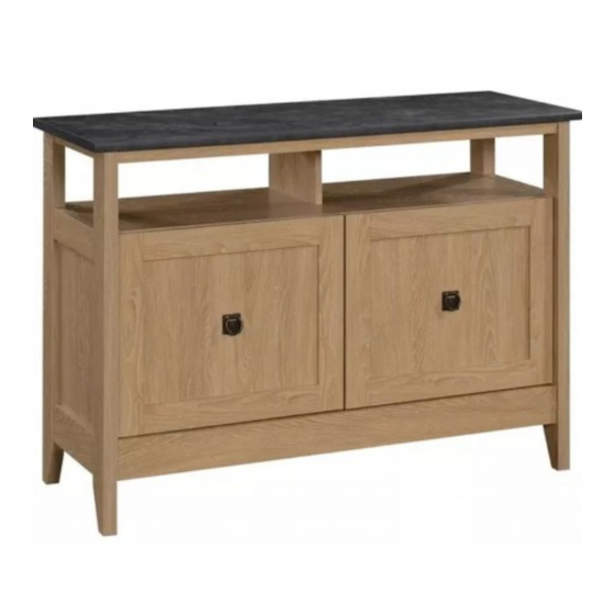
- Page 1 Teknik www.teknikoffice.co.uk Your holder for all things awesome. TV Stand NOTE: THIS INSTRUCTION BOOKLET CONTAINS IMPORTANT SAFETY INFORMATION. Home Study Collection | Model 5426616 PLEASE READ AND KEEP FOR FUTURE REFERENCE.
- Page 2 Table of Contents Assembly Tools Required Part Identifi cation No. 2 Phillips Screwdriver Tip Shown Actual Size Hardware Identifi cation Assembly Steps 6-26 Skip the power trip. Français 27-29 This time. Español 30-32 Safety 33-34 Warranty WARNING Use of a TV that is too heavy or large is hazardous. A TV that is too heavy will create a risk of a tip-over that can cause severe injury or death.
-
Page 3: Part Identification
Now you know Part Identifi cation our ABCs. å While not all parts are labeled, some of the parts will have a label or an inked letter on the edge to help distinguish similar parts from each other. Use this part identifi cation to help identify similar parts. END (2) FIXED SHELF (1) SMALL UPRIGHT (1) -
Page 4: Hardware Identification
Hardware Identifi cation å Screws are shown actual size. You may receive extra hardware with your unit. HIDDEN CAM - 24 CAM DOWEL - 16 CAM SCREW - 8 WOOD DOWEL - 6 14H HINGE - 4 ANGLE BRACKET - 8 WASHER - 2 PULL - 2 WARNING LABEL - 1... - Page 5 Hardware Identifi cation å Screws are shown actual size. You may receive extra hardware with your unit. BLACK 9/16" LARGE HEAD SCREW - 16 BLACK 1/2" FLAT HEAD SCREW - 8 BLACK 9/16" FLAT HEAD SCREW - 8 SILVER 1/4" MACHINE SCREW - 2 118S BLACK 1-3/8"...
- Page 6 Hardware Usage Guide HOW TO USE A HIDDEN CAM & CAM DOWEL Insert the metal end of the CAM DOWEL into the HIDDEN CAM. Cam Dowel Cam Dowel Arrow Hole Hole Push a HIDDEN CAM into Metal end the part. The arrow in the HIDDEN CAM must point toward the hole in the Hidden Cam...
- Page 7 Step 1 Assemble your unit on a carpeted fl oor or on the empty å carton to avoid scratching your unit or the fl oor. Push six HIDDEN CAMS (1F) into the FIXED SHELF (G) å and BACK (M). Then, insert the metal end of a CAM DOWEL (2F) into each HIDDEN CAM.
- Page 8 Step 2 Fasten the FIXED SHELF (G) to the BACK (M). Tighten two å HIDDEN CAMS. i t h f a c S u r D E N H I D Page 8...
- Page 9 Step 3 Fasten the SMALL UPRIGHT (N) to the FIXED SHELF (G). å Use two BLACK 1-15/16" FLAT HEAD SCREWS (113S). Some assembly (and snacks) required. 113S BLACK 1-15/16" FLAT HEAD SCREW (2 used in this step) Page 9...
-
Page 10: Hidden Cam
Step 4 Push two HIDDEN CAMS (1F) into the LARGE UPRIGHT (O). å Then, insert the metal end of a CAM DOWEL (2F) into each HIDDEN CAM. Arrow Do not tighten the HIDDEN CAMS in this step. Metal end (2 used) Page 10... - Page 11 Step 5 Fasten the LARGE UPRIGHT (O) to the FIXED SHELF (G). å Tighten two HIDDEN CAMS. S u r f a c H I D D E N i t h o Page 11...
- Page 12 Step 6 Push four HIDDEN CAMS (1F) into the BOTTOM (H). å Then, insert the metal end of a CAM DOWEL (2F) into each HIDDEN CAM. Arrow Metal end (4 used) Do not tighten the HIDDEN CAMS in this step. Arrow Metal end Page 12...
- Page 13 Step 7 Fasten the BOTTOM (H) to the BACK (M) and LARGE UPRIGHT (O). å Use fi ve BLACK 1-15/16" FLAT HEAD SCREWS (113S). 113S BLACK 1-15/16" FLAT HEAD SCREW (5 used in this step) Page 13...
- Page 14 Step 8 Slide a BOTTOM MOLDING* (L) onto the notched edge of å a BOTTOM (H). *U.S. Patent No. 5,499,886 å Slide the BOTTOM MOLDING (L) onto the notched edge. Notched edge The groove is closer to this edge. Page 14...
- Page 15 Step 9 Turn four BLACK 9/16" FLAT HEAD SCREWS (32S) into the END (A) until the shoulders of the SCREWS rest on the å surfaces of the END. NOTE: Do not overtighten the SCREWS. å Slide the MOLDINGS (J and K) onto the END (A). Line up the grooves in the MOLDINGS over the heads of the SCREWS in å...
- Page 16 Step 10 Insert two WOOD DOWELS (15F) into the LEGS (E and F). å Now might be a Turn four CAM SCREWS (8F) into the LEGS (E and F). å good time to refresh your drink. Flip the LEGS over as shown å...
- Page 17 Step 11 Push four HIDDEN CAMS (1F) into the END (A). å Insert a WOOD DOWEL (15F) into the END (A). å Arrow Fasten the LEGS (E and F). Tighten four HIDDEN CAMS. å NOTE: Be sure the WOOD DOWELS in the LEGS insert å...
- Page 18 Step 12 Fasten the ENDS (A) to the FIXED SHELF (F), å and BOTTOM (H). Tighten eight HIDDEN CAMS. NOTE: Be sure the WOOD DOWELS in the ENDS insert å into the BOTTOM. Page 18...
- Page 19 Step 13 Fasten the BALLAST (Q) to the BOTTOM (H). Use six å BLACK 1-3/8" PAN HEAD SCREWS (118S). 118S BLACK 1-3/8" PAN HEAD SCREW (6 used in this step) Page 19...
- Page 20 Step 14 Fasten eight ANGLE BRACKETS (27G) to the TOP (B). Use å eight BLACK 9/16" LARGE HEAD SCREWS (1S) through the center of the ANGLE BRACKET hole. Push two METAL PINS (1R) into the TOP (B). å BLACK 9/16" LARGE HEAD SCREW (8 used in this step) Page 20...
- Page 21 Step 15 Fasten the TOP (B) to the LEGS (E and F) and SMALL UPRIGHT (N). Tighten four HIDDEN CAMS. å NOTE: Be sure the METAL PINS in the TOP insert into the SMALL UPRIGHT. å Fasten the MOLDINGS (C and D) to the TOP (B). Use eight BLACK 9/16" LARGE HEAD SCREWS (1S) through the ANGLE å...
- Page 22 Step 16 Fasten two HINGES (14H) to one of the DOORS (T). Use å four BLACK 1/2" FLAT HEAD SCREWS (11S). Repeat this step for the remaining door. å BLACK 1/2" FLAT HEAD SCREW (8 used in this step) Page 22...
- Page 23 Step 17 Carefully stand your unit upright. å Pro Tip: Lift with your Before fastening the DOOR to your unit, be sure the mounting screw is å legs. And, you know, against the stops as shown in the right diagram. If it isn't, loosen the your arms.
-
Page 24: Door Adjustments
Step 18 Refer to the enlarged diagram to identify the parts on å the HINGES. The DOORS may need some adjustments. Follow the text below to make needed adjustments. å DOOR ADJUSTMENTS: å To adjust the DOORS from side to side (horizontal), turn the adjusting screw in or out. To adjust the DOORS up and down (vertical), loosen both vertical adjustment screws. - Page 25 Step 19 Push the RUBBER SLEEVES (2R) over the METAL PINS (1R). å Insert the METAL PINS into the hole locations of your choice in the ENDS (A) and LARGE UPRIGHTS (O). Set the ADJUSTABLE SHELVES (P) onto the METAL PINS. Insert the GROMMETS (10P) into the large holes in the BACK (M).
- Page 26 Step 20 Apply the WARNING LABEL (1L) to the TOP (B). You should be able to read the label when the TV is removed from the å unit. Peel off the backing and apply the label as shown in the diagram. NOTE: This is a permanent label intended to last for the life of the product.
- Page 27 WARNING Please use your furniture correctly and safely. Improper use can cause safety hazards, or damage to your furniture or household items. Carefully read the following safety information. Death or serious injury may occur when children climb on audio and/or video equipment furniture. A remote control or toys placed on the furnishing may encourage a child to climb on the furnishing and as a result may tip over onto the child.
Need help?
Do you have a question about the Home Study 5426616 and is the answer not in the manual?
Questions and answers