
Subscribe to Our Youtube Channel
Related Manuals for Baker Hughes Druck DPI 610 IS


Summary of Contents for Baker Hughes Druck DPI 610 IS
- Page 1 DPI 610 / 615 IS Intrinsically Safe Portable Pressure Calibrator Instruction Manual Druck.com...
- Page 3 Read the whole publication before starting. A qualified technician must have the necessary technical knowledge, documentation, special test equipment and tools to carry out the required work on this equipment. Copyright 2007 Baker Hughes Company. English–DPI 610/615 IS Instruction Manual | i...
- Page 4 = 0.05 µF = 0.05 µF a. The output parameters at sockets SK1, SK2 and SK3 do not exceed the values specified in clause 5.7, Simple Apparatus, of EN 60079-11. Copyright 2007 Baker Hughes Company. ii | DPI 610/615 IS Instruction Manual–English...
- Page 5 The DPI 610 IS and DPI 615 IS pressure calibrators are designed and manufactured to meet the essential health and safety requirements not covered by the EU Type Examination Certificate BAS02ATEX1174X when installed as detailed above. Copyright 2007 Baker Hughes Company. English–DPI 610/615 IS Instruction Manual | iii...
- Page 6 Copyright 2007 Baker Hughes Company. iv | DPI 610/615 IS Instruction Manual–English...
-
Page 7: Table Of Contents
Relief Valve Test (REL VALVE) Task Advanced Task General Select Input Ambient Temperature Measurement Process Functions 5.4.1 Tare Process Function 5.4.2 Min/Max Process Function 5.4.3 Filter Process Function 5.4.4 Flow Process Function Copyright 2007 Baker Hughes Company. English–DPI 610/615 IS Instruction Manual | v... - Page 8 Test Equipment Using the Calibration Menu PIN security 8.7.1 Change PIN Calibrate Internal Ranges Internal Pressure Range 8.10 Voltage Input Range (5 V) 8.11 Voltage Input Range (30 V) Copyright 2007 Baker Hughes Company. vi | DPI 610/615 IS Instruction Manual–English...
- Page 9 Appendix A. Datalog File Example Typical Uploaded Data Log File (DPI 610) Typical Uploaded Procedure Data File (DPI 615) Record Type Appendix B. “Quick Fit” Pressure Connector Introduction Connection Sequence Copyright 2007 Baker Hughes Company. English–DPI 610/615 IS Instruction Manual | vii...
- Page 10 Copyright 2007 Baker Hughes Company. viii | DPI 610/615 IS Instruction Manual–English...
-
Page 11: Introduction
Use the Up and Down cursor keys (only) to select the required option. (If all keys shaded, use all these keys to select or enter data). Press the ENTER key. Copyright 2007 Baker Hughes Company. English–DPI 610/615 IS Instruction Manual | 1... -
Page 12: Using This Guide
Table 1-2: Maximum Instrument Rating Parameter Maximum Rating Pressure 120% of full-scale Voltage 30 V dc Current 55 mA dc a. The display flashes if the input pressure, voltage or current over-range. Copyright 2007 Baker Hughes Company. 2 | DPI 610/615 IS Instruction Manual–English... -
Page 13: Operator Controls
A typical display is shown below: TASK : BASIC VOLTAGE PRESSURE INT CURRENT PRESSURE UNITS Status Display Input Display Output Display Soft Boxes Copyright 2007 Baker Hughes Company. English–DPI 610/615 IS Instruction Manual | 3... -
Page 14: Hard Key Functions
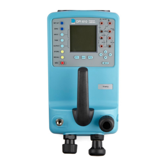
In programs where options need to be selected from a list, (e.g.) the TASK selection program, the up and down cursor keys are used to highlight one of the options, from which it can be Copyright 2007 Baker Hughes Company. 4 | DPI 610/615 IS Instruction Manual–English... - Page 15 Cursor keys Function (soft) keys Release valve (releases pressure through 8) Vent port Select positive or negative pressure Pump Fine pressure adjuster Figure 1-2: DPI 610/615 IS Calibrator Controls Copyright 2007 Baker Hughes Company. English–DPI 610/615 IS Instruction Manual | 5...
-
Page 16: Electrical Connections
Measurement inputs and Source outputs are made via the control panel sockets as shown below: TASK : BASIC INPUTS VOLTAGE OUTPUTS PRESSURE INT PRESSURE CURRENT UNITS Status window Input window Electrical measurement input sockets Output window Figure 1-4: Electrical Measurement Inputs/Source Outputs Copyright 2007 Baker Hughes Company. 6 | DPI 610/615 IS Instruction Manual–English... -
Page 17: Getting Started
Current as input, press F1 as shown. Similarly, F1 to return to Voltage. Note: No other keys are active in this mode and the instrument can only be reconfigured by pressing the TASK key and selecting another mode. Copyright 2007 Baker Hughes Company. English–DPI 610/615 IS Instruction Manual | 7... -
Page 18: Change Pressure Units
DO NOT push bare wires into the sockets. max 30V max 30V 55mA 55mA mA in mA in mA Sink mA Sink Note: See Table 1-2 on page 2 for maximum instrument ratings. Copyright 2007 Baker Hughes Company. 8 | DPI 610/615 IS Instruction Manual–English... -
Page 19: Typical Calibration Set-Up (Pressure To Voltage)
Both the input and output readings can be set to zero by using the ZERO key and if the displayed reading is within 5% of zero. To zero either the INPUT or OUTPUT displays, proceed as follows: Copyright 2007 Baker Hughes Company. English–DPI 610/615 IS Instruction Manual | 9... - Page 20 Chapter 2. Getting Started Copyright 2007 Baker Hughes Company. 10 | DPI 610/615 IS Instruction Manual–English...
-
Page 21: Task Selection
(%rdg or % span). When all test parameters have been set- up, the screen changes to display the input and output and the test results. The test result can Copyright 2007 Baker Hughes Company. English–DPI 610/615 IS Instruction Manual | 11... -
Page 22: Basic Mode (Task Basic)
This instrument will power-up in this mode the first time that it is used. To select BASIC from any other task, press the TASK key and select BASIC and press the ENTER key. BASIC mode is described in Section 2.2. Copyright 2007 Baker Hughes Company. 12 | DPI 610/615 IS Instruction Manual–English... -
Page 23: Taking Measurements
External pressure source (indicator instruments only) Pressure regulator Pressure to voltage device Barrier External supply Safe area • If required, select the output units as described in Section 3.3. Copyright 2007 Baker Hughes Company. English–DPI 610/615 IS Instruction Manual | 13... -
Page 24: Pressure Converter (Pressure To Pressure) Task
• If required, select the output units as described in Section 3.3. • If applicable, turn on Cal Mode and set-up test parameters as detailed in Section 3.4. Copyright 2007 Baker Hughes Company. 14 | DPI 610/615 IS Instruction Manual–English... -
Page 25: Current To Pressure Converter (I-P) Task
• If required, change pressure units with INPUT key. A flashing CHECK LOOP message indicates either an open circuit supply loop (or no external supply). Copyright 2007 Baker Hughes Company. English–DPI 610/615 IS Instruction Manual | 15... -
Page 26: Pressure Switch Test (P-Switch) Task
• Reduce pressure until the switch releases (indicated by the switch symbol). The release pressure is then written to the display and the hysteresis displayed. Copyright 2007 Baker Hughes Company. 16 | DPI 610/615 IS Instruction Manual–English... -
Page 27: Pressure To Display (P-Display) Task
Apply a series of test pressures to the device under test. Enter displayed leading at each pressure and log each point: • After logging final test point, terminate as follows: Copyright 2007 Baker Hughes Company. English–DPI 610/615 IS Instruction Manual | 17... -
Page 28: Leak Test (Leak Test) Task
Close the vent valve and pressurize the device/system to the required LEAK TEST pressure. Press the RUN (F2) key to start the leak test. When completed, the beeper sounds and the • leak test results are written to the display. Copyright 2007 Baker Hughes Company. 18 | DPI 610/615 IS Instruction Manual–English... -
Page 29: Transmitter Simulator (Tx Sim) Task
To change the pressure units, press INPUT and select the required scale units. If the required scale units are not listed, press SETUP, select SETTINGS and proceed as detailed in Section 7.4.1. Copyright 2007 Baker Hughes Company. English–DPI 610/615 IS Instruction Manual | 19... -
Page 30: Relief Valve Test (Rel Valve) Task
Snapshot text. • Open vent valve to release test pressure. Note: If using external pressure supply, isolate supply before opening the vent valve. Copyright 2007 Baker Hughes Company. 20 | DPI 610/615 IS Instruction Manual–English... -
Page 31: Advanced Task
ADVANCED task. If the instrument is in any other mode i.e. BASIC or any other task mode, the input and output displays must first be configured in ADVANCED task. Copyright 2007 Baker Hughes Company. English–DPI 610/615 IS Instruction Manual | 21... -
Page 32: Tare Process Function
VOLTAGE PRESSURE INT PRESSURE INT MAKE READING TARE OFF SETTINGS A VALUE ZERO 5.4.1.2 Tare Off An Entered Value To tare-off an entered value current, proceed as follows: Copyright 2007 Baker Hughes Company. 22 | DPI 610/615 IS Instruction Manual–English... -
Page 33: Min/Max Process Function
FILTERED, CHANGES FILTERED, CHANGES GREATER THAN BAND GREATER THAN BAND BYPASS THE FILTER BYPASS THE FILTER BAND = % FS BAND = % FS CHANGE CHANGE VALUE VALUE Copyright 2007 Baker Hughes Company. English–DPI 610/615 IS Instruction Manual | 23... -
Page 34: Flow Process Function
Note: Left/right arrow keys function as page up/down keys. To change the output units (pressure channels only), select the channel with the cursor keys and press F2 before pressing ENTER. Copyright 2007 Baker Hughes Company. 24 | DPI 610/615 IS Instruction Manual–English... -
Page 35: Electrical Outputs (Loop Power)
Press RUN (F1) to run program. A flashing status display CHECK LOOP indicates a fault in the external loop i.e. supply fault or open circuit. Note: The dwell time at each step is approximately 10 seconds. Copyright 2007 Baker Hughes Company. English–DPI 610/615 IS Instruction Manual | 25... -
Page 36: Ma Ramp
SNAPSHOT MODE PRESSURE INT PRESSURE EXT mA STEP PRESSURE INT mA RAMP OUTPUT mA VALUE NEW VALUE CURRENT • Connect an external power source as shown in Section 5.6. Copyright 2007 Baker Hughes Company. 26 | DPI 610/615 IS Instruction Manual–English... -
Page 37: Define New Task
To clear a user defined task, select TASK and proceed as follows: USER TASKS USER TASKS free free SELECT OPTION free free SAVE CLEAR CLEAR TASK? TASK NEW TASK Copyright 2007 Baker Hughes Company. English–DPI 610/615 IS Instruction Manual | 27... - Page 38 Chapter 5. Advanced Task Copyright 2007 Baker Hughes Company. 28 | DPI 610/615 IS Instruction Manual–English...
-
Page 39: Memory Operations
Select a task, other than BASIC. If using ADVANCED, set-up the required output • parameters. • Use SETUP to select Data Log from the Store Mode Menu (See Section 7.2). Copyright 2007 Baker Hughes Company. English–DPI 610/615 IS Instruction Manual | 29... -
Page 40: Auto Log (Timer)
TRIGGER : KEYPRESS FILE SIZE : 886 bytes FILE SIZE : 886 bytes FILE 1 of 9 DATE: 04/11/99 TIME 10:18 ERASE GRAPH TEXT REVIEW TRANSMIT LOGGED DATA FILE Copyright 2007 Baker Hughes Company. 30 | DPI 610/615 IS Instruction Manual–English... -
Page 41: Uploading Data Log Files
TRIGGER : KEYPRESS FILE SIZE : 886 bytes FILE SIZE : 886 bytes FILE 1 of 9 DATE: 04/11/99 TIME 10:18 ERASE GRAPH TEXT REVIEW TRANSMIT LOGGED DATA FILE Copyright 2007 Baker Hughes Company. English–DPI 610/615 IS Instruction Manual | 31... -
Page 42: Delete Datalog And Procedure Files
After the procedure file has been downloaded, the instrument is usually returned to the LOCAL mode by the last command in the procedure file. If the instrument remains in REMOTE mode, switch it OFF and ON to reset it. Copyright 2007 Baker Hughes Company. 32 | DPI 610/615 IS Instruction Manual–English... -
Page 43: Running Procedure Files
Procedure data files can be displayed either as text (stored screens) or in graphical form. To display as text, select the TEXT option (F1) from the directory and proceed as follows from the Copyright 2007 Baker Hughes Company. English–DPI 610/615 IS Instruction Manual | 33... - Page 44 PC. To display logged data in graphical form, on screen, select GRAPH (F2) from the directory and proceed as follows: DIRECTORY AS FOUND AS LEFT TIME TEXT GRAPH Copyright 2007 Baker Hughes Company. 34 | DPI 610/615 IS Instruction Manual–English...
-
Page 45: Using Set-Up
To select one of the SETTINGS options from the set-up menu, proceed as follows: SELECT OPTION SELECT OPTION SETUP SETTINGS UNITS STORE MODE CONTRAST LANGUAGE SETTINGS RS232 DATE & TIME POWERDOWN CALIBRATION DRY CELL LEVEL Copyright 2007 Baker Hughes Company. English–DPI 610/615 IS Instruction Manual | 35... -
Page 46: Units
SCALING FACTOR CHANGE VALUE 7.4.3 Language Select the LANGUAGE version required from the SETTINGS menu and proceed as follows: LANGUAGE SELECT OPTION ENGLISH FRENCH GERMAN ITALIAN PORTUGUESE SPANISH Copyright 2007 Baker Hughes Company. 36 | DPI 610/615 IS Instruction Manual–English... -
Page 47: Rs232
If selected OFF, auto power off is inhibited and once switched on, the instrument remains ON until it is manually switched OFF. 7.4.6 Calibration Refer to Section 8 for a full description of the calibration procedures. Copyright 2007 Baker Hughes Company. English–DPI 610/615 IS Instruction Manual | 37... -
Page 48: Date And Time (Real Time Clock)
and right keys select the required digit position. SELECT OPTION SET TIME FORMAT: FORMAT: DATE: DATE: TIME: TIME: CHANGE DATE CHANGE TIME FORMAT Copyright 2007 Baker Hughes Company. 38 | DPI 610/615 IS Instruction Manual–English... -
Page 49: Calibration
TASK key to select another mode, e.g. ADVANCED before accessing the CALIBRATION mode. A calibration technician must have the necessary technical knowledge, documentation, special test equipment and tools to carry out the calibration work on this equipment. Copyright 2007 Baker Hughes Company. English–DPI 610/615 IS Instruction Manual | 39... -
Page 50: Test Equipment
The calibration routines are selected from the Settings menu as detailed in Section 7.4. Enter the calibration PIN code, initially set to 4321, press and the display shows the calibration menu. Copyright 2007 Baker Hughes Company. 40 | DPI 610/615 IS Instruction Manual–English... -
Page 51: Pin Security
Note: If calibrating the hydraulic calibrator version, the calibrator must first be primed as detailed in Section 9. Connect the outlet port of the instrument to a pressure standard. Allow the instrument’s temperature to stabilize for a minimum of 1 hour. Copyright 2007 Baker Hughes Company. English–DPI 610/615 IS Instruction Manual | 41... -
Page 52: Voltage Input Range (5 V)
Use the following procedure for calibrating the internal 5 V range: Switch the instrument on, enter CALIBRATION mode and select INT RANGES from the CALIBRATION menu shown in Section 8.8. Copyright 2007 Baker Hughes Company. 42 | DPI 610/615 IS Instruction Manual–English... - Page 53 30V 55mA mA in mA Sink Vs Voltage source Figure 8-1: 5 V Input Range Calibration Circuit Copyright 2007 Baker Hughes Company. English–DPI 610/615 IS Instruction Manual | 43...
-
Page 54: Voltage Input Range (30 V)
RANGE +/- 30V RANGE +/- 30V RANGE +/- 30V Apply nominal zero value Enter Applied Value: Press ENTER key when applied value is stable Store zero point? CHANGE VALUE Copyright 2007 Baker Hughes Company. 44 | DPI 610/615 IS Instruction Manual–English... - Page 55 Verify the instrument calibration by applying the test voltages given in Table 8-3 on page 46 to the voltmeter (after both voltage ranges have been calibrated). Disconnect the calibration/test equipment. Copyright 2007 Baker Hughes Company. English–DPI 610/615 IS Instruction Manual | 45...
-
Page 56: Current Input Range (55 Ma)
RANGE +/- 30V RANGE +/- 30V RANGE +/- 30V Apply nominal zero value Enter Applied Value: Press ENTER key when applied value is stable Store zero point? CHANGE VALUE Copyright 2007 Baker Hughes Company. 46 | DPI 610/615 IS Instruction Manual–English... - Page 57 Press the ENTER key to accept the calibration. Press the EXIT key four times to quit the CALIBRATION and SETUP modes. Verify the instrument calibration by applying the test currents given in Table 8-4 on page 48 to the ammeter. Disconnect the calibration/test equipment. Copyright 2007 Baker Hughes Company. English–DPI 610/615 IS Instruction Manual | 47...
-
Page 58: Current Output Range (24 Ma)
Select CURRENT OUT range for calibration: CALIBRATION SELECT OPTION PRESSURE INT VOLTAGE IN CURRENT IN CURRENT OUT TEMPERATURE Connect a digital ammeter to the instrument as shown below. Copyright 2007 Baker Hughes Company. 48 | DPI 610/615 IS Instruction Manual–English... - Page 59 Verify the instrument’s output current calibration by setting up the loop test currents as shown in Table 8-5 on page 50 and checking the set values against the ammeter standard. Copyright 2007 Baker Hughes Company. English–DPI 610/615 IS Instruction Manual | 49...
-
Page 60: Ambient Temperature Channel
± 0.05% rdg ± 0.01% FS ± 0.05% rdg ± 0.01% FS 11. Disconnect the calibration/test equipment. 8.14 Ambient Temperature Channel Use the following procedure for calibrating the ambient temperature measurement channel: Copyright 2007 Baker Hughes Company. 50 | DPI 610/615 IS Instruction Manual–English... -
Page 61: Calibrate External Sensors
Connect the required external transducer to the EXT TRANSDUCER socket located on the rear of the instrument. Allow the instrument’s temperature and the temperature of the external transducer to stabilize in the calibration environment for a minimum of 1 hour. Copyright 2007 Baker Hughes Company. English–DPI 610/615 IS Instruction Manual | 51... - Page 62 CALIBRATION and SETUP modes. Check the calibration of the external transducer by applying the test pressures as detailed in Table 8.6 on page 40. Copyright 2007 Baker Hughes Company. 52 | DPI 610/615 IS Instruction Manual–English...
-
Page 63: Add External Sensor
Digitally compensated transducers will be downloaded into the directory as soon as the F1 key is operated. Data for other types can be edited by selecting EDIT (F2). If the data cannot be edited a warning message (INVALID ACTION) is displayed. Copyright 2007 Baker Hughes Company. English–DPI 610/615 IS Instruction Manual | 53... - Page 64 Chapter 8. Calibration Copyright 2007 Baker Hughes Company. 54 | DPI 610/615 IS Instruction Manual–English...
-
Page 65: Hydraulic Calibrator Versions
Table 9-1: Recommended Hydraulic Fluids ISO 3448 Approximate Esso Viscosity SAE Viscosity Shell Mobil (Exxon) Grade Classification VG10 Tellus R10 Nuto H10 Velocite No. 6 Tellus T15 VG15 Nuto H15 Tellus V15 Copyright 2007 Baker Hughes Company. English–DPI 610/615 IS Instruction Manual | 55... -
Page 66: Safety Instructions
Use a bonded seal (6) and connect the unit or system under test (7) to the pressure port. WARNING Make sure that the connecting line to the external device or system is capable of withstanding the line pressure to be applied. Copyright 2007 Baker Hughes Company. 56 | DPI 610/615 IS Instruction Manual–English... -
Page 67: Bleeding The System
Close the UUT bleed valve (5) when the priming pump (2) is at the bottom of its stroke (fully pushed in) and slowly wind out the screw-press (3) to its fullest extent to draw in further hydraulic fluid (approx. 7 cm or 0.43 in Copyright 2007 Baker Hughes Company. English–DPI 610/615 IS Instruction Manual | 57... -
Page 68: Operation
If necessary, apply an air line to the priming port to clear any remaining fluid out of the instrument. 9.7 Flushing - Refilling or Changing the Hydraulic Fluid If necessary, to remove any contaminants, flush out the hydraulic system as follows: Copyright 2007 Baker Hughes Company. 58 | DPI 610/615 IS Instruction Manual–English... - Page 69 The instrument is now ready for operation or storage. If storing, apply a label detailing the type of hydraulic fluid contained in the instrument. Note: For long term storage, it is recommended that the instrument be drained and stored empty. Copyright 2007 Baker Hughes Company. English–DPI 610/615 IS Instruction Manual | 59...
- Page 70 Chapter 9. Hydraulic Calibrator Versions Copyright 2007 Baker Hughes Company. 60 | DPI 610/615 IS Instruction Manual–English...
-
Page 71: Appendix A. Datalog File Example
0.77 %span 21/10/2006 16:05:00 17.766 17.106 0.51 %span 21/10/2006 16:06:07 17.812 17.105 0.80 %span 21/10/2006 16:07:49 18.532 17.965 1.00 %span 21/10/2006 16:16:35 20.007 20.212 -1.02 %span 21/10/2006 16:18:23 Copyright 2007 Baker Hughes Company. English–DPI 610/615 IS Instruction Manual | 61... -
Page 72: Typical Uploaded Procedure Data File (Dpi 615)
Combination of all Input Process Functions Combination of all Output Process Functions 1024 mA Step Mode 2048 mA Value Mode 4096 mA Ramp Mode 8192 No Input Selected 16384 No Output Selected Copyright 2007 Baker Hughes Company. 62 | DPI 610/615 IS Instruction Manual–English... -
Page 73: Appendix B. "Quick Fit" Pressure Connector
Procedure to attach the “Quick Fit” pressure connector: Remove the adaptor from the “Quick Fit” pressure connector. Use an applicable seal for the pressure connection: NPT type: Use an applicable sealant on the thread. Copyright 2007 Baker Hughes Company. English–DPI 610/615 IS Instruction Manual | 63... - Page 74 Remove the adaptor from the device under test; use appropriate tools as necessary. Re-attach the adaptor to the “Quick Fit” pressure connector and hand tighten it. Copyright 2007 Baker Hughes Company. 64 | DPI 610/615 IS Instruction Manual–English...
- Page 76 Copyright 2007 Baker Hughes Company. This material contains one or more registered trademarks of Baker Hughes Company and its subsidiaries in one or more countries. All third- party product and company names are trademarks of their respective holders. bakerhughes.com...
Need help?
Do you have a question about the Druck DPI 610 IS and is the answer not in the manual?
Questions and answers