Raymarine ST60 Installation Manual
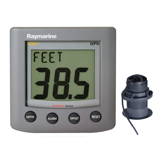
Graphic display
Hide thumbs
Also See for ST60:
- User manual ,
- Owner's handbook manual (64 pages) ,
- Operating manual (38 pages)
Table of Contents
Advertisement
Quick Links
Flush mount template
ST60 Graphic Display
FLUSH MOUNT
Template
Remove material
from shaded area only
Instrument edge
Connection details
SeaTalk cable
Blue
Red
Either:
Data out to NMEA system
or
External alarm signals to Auxiliary Alarm
Use the procedures in the ST60 Graphic
Display Commissioning Guide to set the
function for the NMEA OUT connector.
Drill hole,
6 mm (1/4 in)
UP
diameter in
4 positions
109 mm (4.3 in)
Sun cover edge
SeaTalk cable
Blue
Data in from NMEA
system
6 mm
50 mm
3 mm
ST60 Graphic Display
Installation Guide
Parts supplied
Sun cover
Auxiliary Alarm option
Auxiliary Alarm
Tools required
Power Drill
D6465-1
Site requirements
Check
Red
Running cables
Raymarine Ltd, Portsmouth, Hampshire, UK PO3 5TD
Raymarine Inc. Nashua, NH 03063-4219, USA
Recyclable Material - Please dispose of responsibly.
D6466-1
SeaTalk Cable
Flush mount option
Gasket
ST60 Graphic Display
(ready for
surface mounting)
Connector
block
Grommet
3
/
in (5 mm) Drill
16
Pencil
1
/
in (6 mm) Drill
4
3½ in (90 mm) Hole Cutter
Adhesive tape
Min 9 in (230 mm)
Min 20 in (500 mm)
®
www.raymarine.com
Stud (x2)
Thumb nut (x2)
Connector (x2)
Bracket
Gasket
Bezel
Jig saw
(only required if
flush mounting
the Display)
D6463-1
D6464-2
+44 (0) 23 9269 3611
Toll Free: 800-539-5539
+1 603-881-5200
Advertisement
Table of Contents

Related Manuals for Raymarine ST60


Summary of Contents for Raymarine ST60
-
Page 1: Installation Guide
Either: Data out to NMEA system Data in from NMEA system External alarm signals to Auxiliary Alarm Use the procedures in the ST60 Graphic Display Commissioning Guide to set the function for the NMEA OUT connector. 6 mm 50 mm... - Page 2 ST60 Graphic Display diameter in 2 positions 3 0 .1 3 0 .1 4 4 .6 4 4 .6 (1 .1 (1 .7...
Need help?
Do you have a question about the ST60 and is the answer not in the manual?
Questions and answers