Advertisement
Quick Links
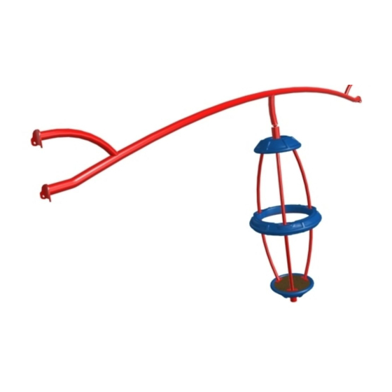
GYRO-POD SPINNER
INSTALLATION INSTRUCTIONS
IMPORTANT NOTES: Read First
(A) Use liquid thread lock (such as Loctite
curing) helps to eliminate the common problem of "thread seizure" in stainless steel hardware by serving as a
lubricant during assembly.
(B) Do not pour concrete until the equipment is completely assembled, leveled and plumbed. Concrete must be
allowed to cure completely before using the equipment (at least 72 hours).
(C) Important: Prior to pouring concrete, verify that the Gyro-Pod spinner spins freely.
(D) Minimum distance from Gyro-Pod Cage to structure shall be no less than 72" [1829mm].
(E) An appropriate energy absorbing safety surface is required under and around all playground equipment.
Loose fill protective surfacing is shown only as an example for the purpose of this assembly instruction. Other
surfacing material may vary in thickness and/or compression depths. See free publication - The Handbook for
Public Playground Safety, Publication #325 at www.cpsc.gov for the surfacing appropriate for the fall height of
the equipment or consult your surfacing supply representative.
Figures 1.1 & 1.4
Figure 1.3
®
) with all threaded hardware. Important: Liquid thread lock (prior to
See Footing Detail
Manufactured by Krauss Craft, Inc.
www.playcraftsystems.com
Gyro-Pod Spinner
Figures 1.2 & 1.5
NOTE: R5 Gyro-Pod Spinner shown.
Other configurations will vary slightly,
but does not affect assembly.
For Customer Service Call
800.333.8519 (U.S.A.) or
541.955.9199 (International)
1974
Page 1 of 9
FIGURE 1
Rev H
1/5/2017
Advertisement

Related Manuals for Playcraft Gyro-Pod Spinner 1974


Summary of Contents for Playcraft Gyro-Pod Spinner 1974
- Page 1 GYRO-POD SPINNER 1974 INSTALLATION INSTRUCTIONS Page 1 of 9 IMPORTANT NOTES: Read First ® (A) Use liquid thread lock (such as Loctite ) with all threaded hardware. Important: Liquid thread lock (prior to curing) helps to eliminate the common problem of "thread seizure" in stainless steel hardware by serving as a lubricant during assembly.
- Page 2 GYRO-POD SPINNER 1974 INSTALLATION INSTRUCTIONS Page 2 of 9 Step 1 Refer to Footing Layout and mark footing hole location. Dig (1) Ø 18" footing hole. Refer to Footing Detail for depth and details. * Footing depth must be adjusted to compensate for the depth/thickness requirements of selected safety surfacing.
- Page 3 GYRO-POD SPINNER 1974 INSTALLATION INSTRUCTIONS Page 3 of 9 R3.5-1974 - Footing Layout 98" 2489mm 21" 533mm R5-1974 - Footing Layout 98" 2489mm " 572mm For Customer Service Call Rev H Manufactured by Krauss Craft, Inc. 800.333.8519 (U.S.A.) or 1/5/2017 www.playcraftsystems.com 541.955.9199 (International)
- Page 4 GYRO-POD SPINNER GYRO-POD SPINNER 1974 1974 INSTALLATION INSTRUCTIONS INSTALLATION INSTRUCTIONS Page 4 of 9 Page 4 of 9 Step 2 (Factory Assembled) Secure Rubber Washer over Ball Joint as shown TOP FRAME in Figure 1.1. 1" x 3" O.D. AR Rubber Washer Figure 1.1 Step 3...
- Page 5 GYRO-POD SPINNER GYRO-POD SPINNER 1974 1974 INSTALLATION INSTRUCTIONS INSTALLATION INSTRUCTIONS Page 5 of 9 Page 5 of 9 Step 5 GYRO-POD HANDRAIL Attach Gyro-Pod Handrails, Ring and Ring Spacers 3/8" x 2" Barrel Nut to Gyro-Pod Ring Plate as shown in Figure 4. (See Note A) 1/2"...
- Page 6 GYRO-POD SPINNER GYRO-POD SPINNER 1974 1974 INSTALLATION INSTRUCTIONS INSTALLATION INSTRUCTIONS Page 6 of 9 Page 6 of 9 Step 7 Refer to Footing detail for collar heights and attach Top Frame to post as shown in Figures 1.2a and 1.2b. (See Note A) R5 SPLIT SPLIT COLLAR HALF...
- Page 7 GYRO-POD SPINNER GYRO-POD SPINNER 1974 1974 INSTALLATION INSTRUCTIONS INSTALLATION INSTRUCTIONS Page 7 of 9 Page 7 of 9 Step 10 Place Gyro-Pod Leg into footing hole and attach Gyro-Pod Bearing Hub to Top Frame as shown BALL JOINT in Figure 1.4. (See Notes A, B, C & D) SOCKET HALF TOP FRAME 1/2"...
-
Page 8: Installation Instructions
GYRO-POD SPINNER 1974 INSTALLATION INSTRUCTIONS Page 8 of 9 R3.5 Parts List R5 Parts List Part # DESCRIPTION QTY. Part # DESCRIPTION QTY. AE-0789 Gyro-Pod Tread Plate AE-0789 Gyro-Pod Tread Plate AE-0790 Gyro-Pod Ring Plate AE-0790 Gyro-Pod Ring Plate BG-8133 Split Collar Half R3.5 BF-7068 Split Collar Half R5... -
Page 9: Specifications
GYRO-POD SPINNER 1974 INSTALLATION INSTRUCTIONS Page 9 of 9 Specifications GYRO-POD LEG: Shall be fabricated using 2.375" O.D. 10 gauge steel tubing with welded 1/4" x 1-1/2" flat steel reinforcement plates and stainless steel ball bearing. The Gyro-Pod Leg shall have a multi-stage baked-on powder coat finish.
Need help?
Do you have a question about the Gyro-Pod Spinner 1974 and is the answer not in the manual?
Questions and answers