Table of Contents
Advertisement
Quick Links
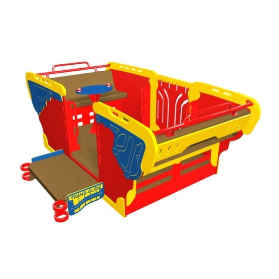
TRANS-GLIDE ASSEMBLY
INSTALLATION INSTRUCTIONS
IMPORTANT NOTES: Read First
(A) Use liquid thread lock (such as Loctite
curing) helps to eliminate the common problem of "thread seizure" in stainless steel hardware by serving as a
lubricant during assembly.
(B) Concrete must be allowed to cure completely before installing the equipment (at least 72 hours).
(C) Refer to Installation Manual for R5-09 Collars and R5-11 Socket Clamps installation instructions.
(D) Follow the installation procedure for expansion anchors (min. 1/2" x 5-1/2") as provided by the manufacturer.
Expansion anchors and hardware are not included with assembly.
(E) Important: Gap between Trans-Glide Deck and Transition Deck must be between 1-1/8" [29mm] to 1-1/4"
[32mm]. The top of Trans-Glide Deck to top of Transition Deck must be flush
(F) An appropriate energy absorbing safety surface is required under and around all playground equipment.
Loose fill protective surfacing is shown only as an example for the purpose of this assembly instruction. Other
surfacing material may vary in thickness and/or compression depths. See free publication - The Handbook for
Public Playground Safety, Publication #325 at www.cpsc.gov for the surfacing appropriate for the fall height of
the equipment or consult your surfacing supply representative.
See Installation Manual
Sections R5-09 Collars
and R5-11 Clamps
Figure 1.1
®
) with all threaded hardware. Important: Liquid thread lock (prior to
Manufactured by Krauss Craft, Inc.
www.playcraftsystems.com
Page 1 of 19
1/4" [6mm].
See Footing Detail
For Customer Service Call
800.333.8519 (U.S.A.) or
541.955.9199 (International)
1975
FIGURE 1
Trans-Glide
Rev B
10/13/2016
Advertisement
Table of Contents

Related Manuals for Playcraft Trans-Glide 1975


Summary of Contents for Playcraft Trans-Glide 1975
- Page 1 TRANS-GLIDE ASSEMBLY 1975 INSTALLATION INSTRUCTIONS Page 1 of 19 IMPORTANT NOTES: Read First ® (A) Use liquid thread lock (such as Loctite ) with all threaded hardware. Important: Liquid thread lock (prior to curing) helps to eliminate the common problem of "thread seizure" in stainless steel hardware by serving as a lubricant during assembly.
- Page 2 TRANS-GLIDE ASSEMBLY 1975 INSTALLATION INSTRUCTIONS Page 2 of 19 Step 1 Footing Detail LOOSE FILL SURFACING MATERIAL SHOWN: Refer to Footing Layout and mark footing hole 9" compressed or 12" uncompressed depth. Compressed depth shown. (See Note F) location. Dig (1) 86-5/8" x 51-1/4" footing hole. Deck Gap Refer to Footing Detail for depth and details.
- Page 3 TRANS-GLIDE ASSEMBLY 1975 INSTALLATION INSTRUCTIONS Page 3 of 19 Step 3 (Factory Assembled) WHEEL HUB SEALED BALL BEARING Press Sealed Ball Bearings into Track Wheels TRACK WHEEL and attach to Wheel Hubs as shown in Figure 2. SEALED BALL BEARING 1"...
- Page 4 TRANS-GLIDE ASSEMBLY 1975 INSTALLATION INSTRUCTIONS Page 4 of 19 Step 7 (Factory Assembled) Install Nutserts to Trans-Glide Base as shown in Figure 6. (See Note A) TRANS-GLIDE BASE 3/8" Nutsert Step 8 FIGURE 6 (Factory Assembled) Slide Trans-Glide Deck into Base and attach Bumpers to Trans-Glide Base as shown in Figure 7.
-
Page 5: Wheel Hub
TRANS-GLIDE ASSEMBLY 1975 INSTALLATION INSTRUCTIONS Page 5 of 19 Step 10 3/8" x 1-1/2" (Factory Assembled) Button Head Bolt 3/8" x 1" O.D. Attach Torsion Bracket to Passenger Side Wheel Washer Hub as shown in Figure 9. (See Note A) TORSION BRACKET WHEEL HUB 3/8"... - Page 6 TRANS-GLIDE ASSEMBLY 1975 INSTALLATION INSTRUCTIONS Page 6 of 19 3/8" x 1-1/4" Step 13 Button Head Bolt (Factory Assembled) 3/8" x 7/8" O.D. Washer 3/8" x 2" Assemble Grips to Trans-Glide Handle and attach Barrel Nut to Driveshaft as shown in Figure 12. (See Note A) 1/2"...
- Page 7 TRANS-GLIDE ASSEMBLY 1975 INSTALLATION INSTRUCTIONS Page 7 of 19 Step 16 3/8" x 5/8" Barrel Nut (Factory Assembled) BACK SIDE 1/2" SAE Washer PANEL 3/8" x 7/8" O.D. Attach Back Accents to Back Side Panels as shown Washer in Figure 15. (See Note A) 3/8"...
-
Page 8: Front Handle
TRANS-GLIDE ASSEMBLY 1975 INSTALLATION INSTRUCTIONS Page 8 of 19 Step 19 FRONT HANDLE (Factory Assembled) 1/2" SAE Washer FRONT GUARD Attach Front Handles and Guards to Front Side Panels 3/8" x 5/8" as shown in Figure 18. (See Note A) 3/8"... - Page 9 TRANS-GLIDE ASSEMBLY 1975 INSTALLATION INSTRUCTIONS Page 9 of 19 Step 22 (Factory Assembled) Insert Driveshaft into Drive House and attach Snap Ring. Attach Drive Plate to Driveshaft as shown in Figure 21. (See Note A) SNAP RING DRIVESHAFT DRIVE PLATE 9/16"...
- Page 10 TRANS-GLIDE ASSEMBLY 1975 INSTALLATION INSTRUCTIONS Page 10 of 19 Step 26 MOUNTING BLOCK 3/8" x 2-1/2" Button Head Bolt 3/8" x 1" O.D. Attach Trans-Glide Transition Deck to collars as shown Washer in Figure 25. (See Note A) TRANS-GLIDE TRANSITION DECK 1/2"...
- Page 11 TRANS-GLIDE ASSEMBLY 1975 INSTALLATION INSTRUCTIONS Page 11 of 19 Step 30 Attach Base Caps to Trans-Glide Base as shown in Figure 28. NOTE: Do not use liquid thread lock. ® (such as Loctite 3/8" x 1-1/2" 3/8" x 1" O.D. SPRING RIDER Button Head Bolt TRANS-GLIDE...
- Page 12 TRANS-GLIDE ASSEMBLY 1975 INSTALLATION INSTRUCTIONS Page 12 of 19 Step 33 3/8" x 1-1/2" Button Head Bolt Attach Back and Front Side Panels and Deck Spacer 3/8" x 7/8" O.D. to Trans-Glide Deck as shown in Figure 31. Washer (See Note A) 3/8"...
- Page 13 TRANS-GLIDE ASSEMBLY 1975 INSTALLATION INSTRUCTIONS Page 13 of 19 Step 36 Attach Back and Front Side Panels and Door to Trans-Glide Deck as shown in Figure 34. (See Note A) BACK SIDE PANEL 3/8" x 2-1/4" TRANS-GLIDE Button Head Bolt DECK 3/8"...
- Page 14 TRANS-GLIDE ASSEMBLY 1975 INSTALLATION INSTRUCTIONS Page 14 of 19 DOOR PANEL Step 39 BACK SIDE PANEL Attach Back and Front Deck Trim to Panels and Trans-Glide Deck as shown in Figure 37. (See Note A) BACK DECK TRIM TRANS-GLIDE DECK 3/8"...
- Page 15 TRANS-GLIDE ASSEMBLY 1975 INSTALLATION INSTRUCTIONS Page 15 of 19 Step 42 Attach Bench Backs and Seats to Side Panels as shown in Figure 40. (See Note A) BENCH BACK 3/8" x 1" O.D. Washer 1/2" SAE Washer 3/8" x 1-3/4" 3/8"...
- Page 16 TRANS-GLIDE ASSEMBLY 1975 INSTALLATION INSTRUCTIONS Page 16 of 19 Step 45 Attach Seat Panels to Bench Backs and Side Panels as shown in Figure 43. (See Note A) 3/8" x 7/8" O.D. Step 46 Washer 3/8" x 1-1/2" Button Head Bolt 1/2"...
-
Page 17: Installation Instructions
TRANS-GLIDE ASSEMBLY 1975 INSTALLATION INSTRUCTIONS Page 17 of 19 Assembled Parts List Part # DESCRIPTION Part # DESCRIPTION 561234 2" x 3/4"L Flanged Bearing AE-0425 Trans-Glide Drive Plate AE-0426 Trans-Glide Drive Arm 9103032-TR Bolt Button Head 3/8" x 3/4" AE-0452 2"... -
Page 18: Parts List
TRANS-GLIDE ASSEMBLY 1975 INSTALLATION INSTRUCTIONS Page 18 of 19 Parts List Specifications RETAINER PLATE: Part # DESCRIPTION Shall be precision cut from 1/4" thick steel. The BE-4466 Spring Rider Bracket Retainer Plate shall have a multi-stage baked-on CE-0444-B Trans-Glide Bench - Back powder coat finish. - Page 19 TRANS-GLIDE ASSEMBLY 1975 INSTALLATION INSTRUCTIONS Page 19 of 19 Specifications TRANS-GLIDE DAMPENER PLATE: MOUNTING BLOCKS: Shall be made from Ultra High Molecular Weight Shall be two-part and precision die-cast from a high Polyethylene for lasting durability. strength aluminum alloy. The Mounting Blocks have a multi-stage baked-on powder coat finish.
Need help?
Do you have a question about the Trans-Glide 1975 and is the answer not in the manual?
Questions and answers