Table of Contents
Advertisement
Quick Links
Model No. PFEL04813.2
Serial No.
USER'S MANUAL
Write the serial number in the space
above for reference.
Serial Number Decal
ACTIVATE YOUR
WARRANTY
To register your product and
activate your warranty today,
go to www.proformservice.com/
registration.
CUSTOMER CARE
For service at any time, go to
www.proformservice.com.
Or call 1-888-533-1333
Mon.–Fri. 6 a.m.–6 p.m. MT
Sat. 8 a.m.–12 p.m. MT
Please do not contact the store.
CAUTION
Read all precautions and instruc-
tions in this manual before using
this equipment. Keep this manual
for future reference.
Advertisement
Table of Contents

Related Manuals for Pro-Form EASY STRIDER


Summary of Contents for Pro-Form EASY STRIDER
- Page 1 Model No. PFEL04813.2 Serial No. USER’S MANUAL Write the serial number in the space above for reference. Serial Number Decal ACTIVATE YOUR WARRANTY To register your product and activate your warranty today, go to www.proformservice.com/ registration. CUSTOMER CARE For service at any time, go to www.proformservice.com.
-
Page 2: Table Of Contents
TABLE OF CONTENTS WARNING DECAL PLACEMENT ............. . .2 IMPORTANT PRECAUTIONS . -
Page 3: Important Precautions
IMPORTANT PRECAUTIONS WARNING: To reduce the risk of serious injury, read all important precautions and instructions in this manual and all warnings on your elliptical before using your elliptical. ICON assumes no responsibility for personal injury or property damage sustained by or through the use of this product. - Page 4 STANDARD SERVICE PLANS...
-
Page 5: Before You Begin
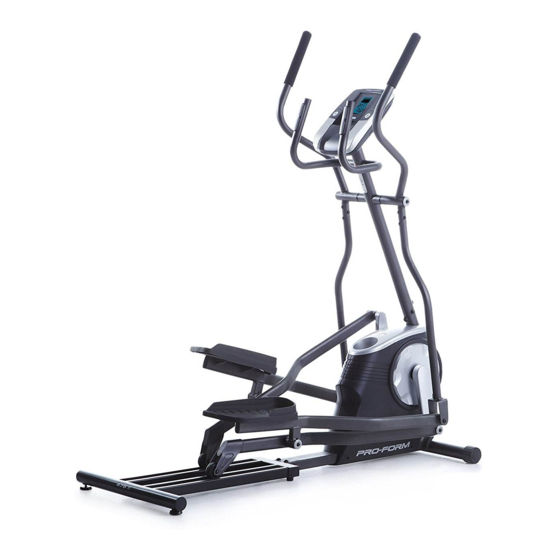
Thank you for selecting the revolutionary PROFORM reading this manual, please see the front cover of this ® EASY STRIDER elliptical. The EASY STRIDER manual. To help us assist you, note the product model elliptical provides an impressive selection of features number and serial number before contacting us. -
Page 6: Part Identification Chart
PART IDENTIFICATION CHART Use the drawings below to identify the small parts needed for assembly. The number in parentheses below each drawing is the key number of the part, from the PART LIST near the end of this manual. The number following the key number is the quantity needed for assembly. -
Page 7: Assembly
ASSEMBLY • To hire an authorized service technician to • To identify small parts, see page 6. assemble this product, call 1-800-445-2480. • In addition to the included tool(s), assembly • Assembly requires two persons. requires the following tools: one Phillips screwdriver •... - Page 8 3. With the help of a second person, place some of the packing materials (not shown) under the rear of the Frame (1). Attach the Track (11) to the Frame (1) with four M10 x 20mm Screws (74), two M10 x 38mm Screws (75), and six M10 Washers (64) as shown;...
- Page 9 5. Tip: Avoid pinching the Main Wire (32). Slide the Upright (2) onto the Frame (1). Attach the Upright (2) with an M10 x 53mm Avoid pinching Screw (73), an M10 x 20mm Screw (74), two the Main Wire M10 Split Washers (80), and two M10 Curved (32) Washers (62) as shown;...
- Page 10 7. Identify the Right Upper Body Arm (4) and the Right Upper Body Leg (5), and orient them as shown. Insert the Right Upper Body Arm (4) into the Right Upper Body Leg (5). Attach the Right Upper Body Arm with three M8 x 38mm Bolts (59) and three M8 Locknuts (60);...
- Page 11 9. Apply grease to the right Crank Arm (13). Next, identify the Right Roller Arm (7), orient it as shown, and slide it onto the right Crank Arm (13). Attach the Right Roller Arm (7) with an M8 x 20mm Screw (61), an Axle Cover (44), and an Grease M8 Washer (63).
- Page 12 11. Apply grease to an M6 Bolt Set (67). Attach the Right Pedal Arm (9) to the Right Upper Body Leg (5) with the M6 Bolt Set (67). Attach the Left Pedal Arm (10) to the Left Upper Body Leg (6) in the same way. Grease 12.
- Page 13 13. Remove and discard the wire tie on the Main Wire (32). Have a second person hold the Console (30) near the Upright (2). Avoid pinching the wires Connect the wires on the Console (30) to the Main Wire (32) and to the Pulse Wire (31). Insert the excess wire into the Upright (2).
-
Page 14: How To Use The Elliptical
HOW TO USE THE ELLIPTICAL HOW TO MOVE THE ELLIPTICAL HOW TO EXERCISE ON THE ELLIPTICAL Due to the size and weight of the elliptical, moving To mount the elliptical, hold the handlebars or the it requires two persons. Stand in front of the elliptical, upper body arms and step onto the pedal that is in the hold the upright, and place one foot against one of the lower position. - Page 15 CONSOLE DIAGRAM FEATURES OF THE CONSOLE The console offers eighteen preset workouts—nine weight loss and nine performance workouts. Each The advanced console offers an array of features preset workout automatically changes the resistance designed to make your workouts more effective and of the pedals as it guides you through an effective enjoyable.
- Page 16 HOW TO USE THE MANUAL MODE Profile—When a workout is selected, this display mode will show a profile of the resistance settings 1. Turn on the console. of the workout. Pulse—This display mode will show your heart rate Press any button or begin pedaling to turn on the console.
- Page 17 5. Measure your heart rate if desired. Note: If the pedals do not move for about thirty seconds, the fan will turn off automatically. If there are sheets of plastic on the metal 7. When you are finished exercising, the console contacts on the will turn off automatically.
- Page 18 HOW TO USE AN 8-WEEK WEIGHT-LOSS segment of the workout. The height of the flashing WORKOUT segment indicates the resistance level for the cur- rent segment. 1. Turn on the console. At the end of each segment of the workout, a Press any button or begin pedaling to turn on the series of tones will sound and the next segment of console.
- Page 19 HOW TO USE A PRESET WORKOUT At the end of each segment of the workout, a series of tones will sound and the next segment of 1. Turn on the console. the profile will begin to flash. If a different resis- tance level is programmed for the next segment, Press any button or begin pedaling to turn on the the resistance level will flash in the display for a...
-
Page 20: Fcc Information
FCC INFORMATION This equipment has been tested and found to comply with the limits for a Class B digital device, pursuant to part 15 of the FCC Rules. These limits are designed to provide reasonable protection against harmful interference in a residential installation. This equipment generates, uses, and can radiate radio frequency energy and, if not installed and used in accordance with the instructions, may cause harmful interference to radio communications. -
Page 21: Maintenance And Troubleshooting
MAINTENANCE AND TROUBLESHOOTING MAINTENANCE Next, locate the Reed Switch (33). Turn the Pulley (15) until a Magnet (65) is aligned with the Reed Switch. Inspect and tighten all parts of the elliptical regularly. Replace any worn parts immediately. To clean the elliptical, use a damp cloth and a small amount of mild soap. - Page 22 HOW TO ADJUST THE DRIVE BELT See EXPLODED DRAWING A on page 26. Remove the M4 x 25mm Screw (68) and the M4 x 19mm If the pedals slip while you are pedaling, even while Screws (84) from the Right and Left Shields (48, 49); make sure to note the location of each Screw.
-
Page 23: Exercise Guidelines
EXERCISE GUIDELINES Burning Fat—To burn fat effectively, you must exer- WARNING: cise at a low intensity level for a sustained period of Before beginning this time. During the first few minutes of exercise, your or any exercise program, consult your physi- body uses carbohydrate calories for energy. - Page 24 SUGGESTED STRETCHES The correct form for several basic stretches is shown at the right. Move slowly as you stretch; never bounce. 1. Toe Touch Stretch Stand with your knees bent slightly and slowly bend forward from your hips. Allow your back and shoulders to relax as you reach down toward your toes as far as possible.
-
Page 25: Part List
PART LIST Model No. PFEL04813.2 R0115A Key No. Qty. Description Key No. Qty. Description Frame Large Round Cap Upright Right Pedal Left Upper Body Arm Left Pedal Right Upper Body Arm Right Shield Right Upper Body Leg Left Shield Left Upper Body Leg Accessory Tray Right Roller Arm V-clip... -
Page 26: Exploded Drawing
EXPLODED DRAWING A Model No. PFEL04813.2 R0115A... - Page 27 EXPLODED DRAWING B Model No. PFEL04813.2 R0115A...
-
Page 28: Ordering Replacement Parts
ORDERING REPLACEMENT PARTS To order replacement parts, please see the front cover of this manual. To help us assist you, be prepared to provide the following information when contacting us: • the model number and serial number of the product (see the front cover of this manual) •...
Need help?
Do you have a question about the EASY STRIDER and is the answer not in the manual?
Questions and answers