Table of Contents
Advertisement
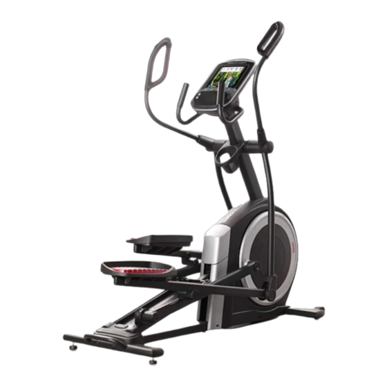
Model No. PFEL78821-INT.0
Serial No.
Write the serial number in the space
above for reference.
Serial Number
Decal
MEMBER CARE
UNITED KINGDOM
Call: 0330 123 1045
From Ireland: 053 92 36102
Website: iconsupport.eu
E-mail: csuk@iconeurope.com
Write:
ICON Health & Fitness, Ltd.
Unit 4, Westgate Court
Silkwood Park
OSSETT
WF5 9TT
UNITED KINGDOM
AUSTRALIA
Call: 1800 993 770
E-mail: australiacc@iconfitness.com
Write:
iFIT Inc.
PO Box 635
WINSTON HILLS NSW 2153
AUSTRALIA
CAUTION
Read all precautions and
instructions in this manual before
using this equipment. Keep this
manual for future reference.
USER'S MANUAL
iconeurope.com
Advertisement
Table of Contents

Related Manuals for Pro-Form TRAINER EL5


Summary of Contents for Pro-Form TRAINER EL5
- Page 1 Model No. PFEL78821-INT.0 Serial No. USER’S MANUAL Write the serial number in the space above for reference. Serial Number Decal MEMBER CARE UNITED KINGDOM Call: 0330 123 1045 From Ireland: 053 92 36102 Website: iconsupport.eu E-mail: csuk@iconeurope.com Write: ICON Health & Fitness, Ltd. Unit 4, Westgate Court Silkwood Park OSSETT...
-
Page 2: Table Of Contents
TABLE OF CONTENTS WARNING DECAL PLACEMENT ............. . .2 IMPORTANT PRECAUTIONS . -
Page 3: Important Precautions
IMPORTANT PRECAUTIONS WARNING: To reduce the risk of burns, fire, electric shock, or injury to persons, read all important precautions and instructions in this manual and all warnings on your elliptical before using your elliptical. iFIT assumes no responsibility for personal injury or property damage sus- tained by or through the use of this product. - Page 4 18. The elliptical does not have a freewheel; the 20. Over exercising may result in serious injury pedals will continue to move until the fly- or death. If you feel faint, if you become short wheel stops. Reduce your pedaling speed in of breath, or if you experience pain while a controlled way.
-
Page 5: Before You Begin
Thank you for selecting the revolutionary PROFORM reading this manual, please see the front cover of this TRAINER EL5 elliptical. The TRAINER EL5 elliptical manual. To help us assist you, note the product model provides an impressive selection of features designed number and serial number before contacting us. -
Page 6: Part Identification Chart
PART IDENTIFICATION CHART Use the drawings below to identify the small parts needed for assembly. The number in parentheses below each drawing is the key number of the part, from the PART LIST near the end of this manual. The number following the key number is the quantity needed for assembly. -
Page 7: Assembly
ASSEMBLY • Assembly requires two persons. • In addition to the included tool(s), assembly requires the following tools: • Place all parts in a cleared area and remove the one Phillips screwdriver packing materials. Do not dispose of the packing materials until you fi... - Page 8 3. With the help of a second person, place some of the packing materials (not shown) under the front of the Frame (1). Have the second per- son hold the Frame to prevent it from tipping while you complete this step. If there are shipping supports attached to the front of the Frame (1), remove the screws from the shipping supports, and discard the screws...
- Page 9 5. Tip: Avoid pinching the Upper Wire (110). Have a second person hold the Upright (4) on Avoid pinching the the Frame (1). Upper Wire (110) Tip: Two M10 x 25mm Screws (92) are preattached to the Frame (1). Attach the Upright (4) to the Frame (1) with two additional M10 x 25mm Screws (92);...
- Page 10 7. Using a plastic bag to keep your fingers clean, apply grease to the axle on the right side of the Upright (4). Next, slide a Pivot Spacer (54) onto the right 4 Grease side of the Upright (4). Then, identify the Right Upper Body Leg (60), orient it as shown, and slide it onto the right side of the Upright (4).
- Page 11 9. Apply grease to a Pedal Arm Axle (64). Insert the Pedal Arm Axle (64) into the Right Upper Body Leg (60) and the Right Pedal Arm (58) from the direction shown. Next, slide an M8 x 22mm Washer (129) onto an M8 x 13mm Screw (82), and tighten the Screw a few turns into the Pedal Arm Axle (64).
- Page 12 11. Orient the Rear Console Cover (80) as shown, and attach it to the Upright (4) with two M4 x 16mm Screws (101). Then, orient the Front Console Cover (79) as shown, and attach it to the Rear Console Cover (80) with two M4 x 16mm Screws (101).
- Page 13 13. Orient a Lower Tray Cover (81) as shown, and attach it to the right side of the Accessory Tray (37) with two M4 x 16mm Screws (101). Repeat this step on the other side of the elliptical. 14. Identify the Right Upper Body Arm (61), orient it as shown, and insert it into the Right Upper Body Leg (60).
- Page 14 15. Orient the Front Shield Cover (117) and the Center Shield Cover (75) around the Upright (4). Then, attach them to each other with two M4 x 16mm Screws (101). Tip: Avoid pinching the wires. Press the Front Avoid pinching Shield Cover (117) and the Center Shield Cover the wires (75) into the Left and Right Shields (73, 74).
- Page 15 17. Orient the Right Arm Front and Rear Covers (65, 66) around the Right Upper Body Leg (60) as shown, and then attach them with two M4 x 16mm Screws (101). Repeat this step on the other side of the elliptical.
-
Page 16: How To Plug In The Power Cord
HOW TO PLUG IN THE POWER CORD This product must be earthed. If it should Follow the steps below to plug in the power cord. malfunction or break down, earthing provides a path of least resistance for electric current to reduce the risk 1. -
Page 17: How To Use The Elliptical
HOW TO USE THE ELLIPTICAL HOW TO MOVE THE ELLIPTICAL HOW TO LEVEL THE ELLIPTICAL Due to the size and weight of the elliptical, moving If the elliptical rocks slightly on your floor during use, it requires two persons. Take any necessary turn one or both of the leveling feet (D) beneath measures to protect your floor. - Page 18 HOW TO EXERCISE ON THE ELLIPTICAL To mount the elliptical, hold the handlebars (G) or the upper body arms (H) and step onto the pedal (I) that is in the lower position. Then, step onto the other pedal. Push the pedals until they begin to move with a con- tinuous motion.
-
Page 19: How To Use The Console
HOW TO USE THE CONSOLE CONSOLE DIAGRAM FEATURES OF THE CONSOLE With the iFIT app, you can access a large and varied library of iFIT video workouts, create your own work- The advanced console offers an array of features outs, track your workout results, and access many designed to make your workouts more effective and other features. - Page 20 HOW TO TURN ON THE CONSOLE HOW TO USE THE MANUAL MODE IMPORTANT: If the elliptical has been exposed to 1. Begin pedaling or press any button on the cold temperatures, allow it to warm to room tem- console to turn on the console. perature before you turn on the console.
- Page 21 4. Follow your progress with the displays. Multi-scan button (B); the scan indicator (D) and the word SCAN will turn on in the display. The display can show the following workout information: Calories (CALS)—The approximate number of calories you have burned. Calories per Hour (CALS/HR)—The approximate number of calories you are burning per hour.
- Page 22 5. Wear a compatible heart rate monitor and HOW TO USE THE SOUND SYSTEM measure your heart rate if desired. To play music or audio books through the console You can wear a compatible heart rate monitor to sound system while you exercise, plug a 3.5 mm male measure your heart rate.
- Page 23 HOW TO USE AN IFIT WORKOUT When a connection is established, the LED on the console will turn solid blue. The console offers access to a large and varied library of iFIT workouts when you download the iFIT app to 4.
- Page 24 IMPORTANT: The calorie goal shown in the HOW TO CONNECT YOUR HEART RATE MONITOR workout description is an estimate of the TO THE CONSOLE number of calories that you will burn during the workout. The actual number of calories The console is compatible with all Bluetooth Smart that you burn will depend on various factors, heart rate monitors.
- Page 25 HOW TO CHANGE CONSOLE SETTINGS Unit of Measurement—The currently selected unit of measurement will appear in the display. The 1. Select the settings mode. console can show speed and distance in standard or metric units of measurement. To change the unit To select the settings mode, press the Settings of measurement, press the Std/Met button repeat- button.
- Page 26 Total Distance—The letters MI or KM will appear Demo Mode—The currently selected demo mode in the display. The display will show the total option will appear in the display. The console distance (in miles or kilometers) that the elliptical features a demo mode, designed to be used if the has been pedaled.
-
Page 27: Maintenance And Troubleshooting
MAINTENANCE AND TROUBLESHOOTING MAINTENANCE Locate the Reed Switch (38). Turn the Pulley (19) until a Magnet (43) is aligned with the Reed Switch. Regular maintenance is important for optimal performance and to reduce wear. Inspect and properly tighten all parts each time the elliptical is used. - Page 28 HOW TO ADJUST THE DRIVE BELT Next, locate and loosen the If the pedals slip while you are pedaling, even while Idler Screw (89). the resistance is adjusted to the highest level, the drive Tighten the Drive belt may need to be adjusted. To adjust the drive belt, Belt Adjustment first unplug the power cord.
-
Page 29: Exercise Guidelines
EXERCISE GUIDELINES Aerobic Exercise—If your goal is to strengthen your WARNING: cardiovascular system, you must perform aerobic Before beginning this exercise, which is activity that requires large amounts or any exercise program, consult your physi- of oxygen for prolonged periods of time. For aerobic cian. - Page 30 SUGGESTED STRETCHES The correct form for several basic stretches is shown at the right. Move slowly as you stretch; never bounce. 1. Toe Touch Stretch Stand with your knees bent slightly and slowly bend forward from your hips. Allow your back and shoulders to relax as you reach down toward your toes as far as possible.
-
Page 31: Part List
PART LIST Model No. PFEL78821-INT.0 R1021A Key No. Qty. Description Key No. Qty. Description Frame/Ramp Roller Rear Stabilizer Left Pedal Handle Access Cover Axle Cover Upright Pivot Spacer M4 x 19mm Screw Retainer Front Stabilizer Roller Arm Bushing Console Pedal Arm Bearing Roller Guide Right Pedal Arm Crank Bearing Sleeve... - Page 32 Key No. Qty. Description Key No. Qty. Description M4 x 16mm Screw M8 x 20mm Flat Head Screw M8 Locknut Frame Bushing M6 x 12mm Screw M10 x 47mm Bolt M10 x 115mm Screw Outer Arm Bearing M4 x 25mm Flange Screw M4 x 16mm Machine Screw Lower Ramp Cover Right Upper Grip...
-
Page 33: Exploded Drawing
EXPLODED DRAWING A Model No. PFEL78821-INT.0 R1021A... - Page 34 EXPLODED DRAWING B Model No. PFEL78821-INT.0 R1021A...
- Page 35 EXPLODED DRAWING C Model No. PFEL78821-INT.0 R1021A...
-
Page 36: Ordering Replacement Parts
ORDERING REPLACEMENT PARTS To order replacement parts, please see the front cover of this manual. To help us assist you, be prepared to provide the following information when contacting us: • the model number and serial number of the product (see the front cover of this manual) •...
Need help?
Do you have a question about the TRAINER EL5 and is the answer not in the manual?
Questions and answers