
Related Manuals for RTA Products Techni Mobili RTA-8408


Summary of Contents for RTA Products Techni Mobili RTA-8408
- Page 1 ASSEMBLY INSTRUCTIONS Thanks for purchasing one of our products. Please read carefully the assembly instructions before the installation. Do not discard this manual or any of the packaging material until the unit has been completely assembled.
- Page 2 ▪...
- Page 3 ▪ PART QTY. ITEM 42Pcs Wooden Pin Cam Lock & 34Sets Bolt Sets 26Pcs Hole Covers 8Pcs Screw - 3.5 x 16mm Screw - 5 x 8mm 8Pcs (Euro Screw) 8Pcs Screw TP 10#x1/2'' 12Pcs Screw - 4 x 38mm Door Hinge Set 2Sets (Both parts come...
- Page 4 RTA-8408 HOW TO ASSEMBLE PARTS USING CAM BOLTS AND CAM LOCKS. ☛ This is not an assembly step; it is a guide for when you are actually doing the assembly using this kind of hardware. Cam Lock Cam Bolt 1. Screw the bolt into the corresponding panel.
- Page 6 ▪ Install 42pcs of Wooden Pins (1) into all panels as shown. Use a wooden or light rubber hammer to avoid damage to the pins. Please pay close attention to which holes you have to use, and do not join any parts yet! ▪...
- Page 7 "L" Shaped Flat Shaped Separate the 8 pieces of the sliders (12) according to their shape: - The flat shaped will be used in the next step (4 pieces, both left and right). - The “L” shaped will be used until step 15 (4 pieces, left and right). The back end of the panels have the grove - Install the flat shaped sliders (12) on panels (C) and (D) using screws (5) as shown.
- Page 8 Assemble the leg panels (J) to (L) and (K) to (M) using Cam locks and bolts (2) as shown and as explained in Page 4. First assemble the bottom panel (E) to the left panel (B) using cam locks (2) as shown and explained in page 4, then install the leg panels (H) to the left panel (B) as shown.
- Page 9 ▪ Assemble the middle panel (D) to the bottom panel (E) using screws (7) as shown PAY ATTENTION TO THE ORIENTATION OF THE PANEL: SMOOTH SURFACE FACES TO THE TOP, SURFACE WITH THE HOLES FACES TO THE BOTTOM. ▪ Assemble the partition panel (F) to the middle panel (D) using cam locks (2) as shown and explained in page 4.
- Page 10 ▪ Assemble the right panel (C) to the bottom panel (E) and the partition panel (F) using cam locks (2) as shown and explained in page 4. ▪ Insert the back panels (W) and (X) into the groves of the panels (B), (C), (D) and (E) as shown.
- Page 11 ▪ Assemble the main panel (A) to the panels (B), (C) And (D) using cam locks (2) as shown and explained in page 4. ▪ Assemble panel (J) ,(L) ,(M) , & (K) with Cam Lock (2) as shown above. Then attach the plastic feet (10) to the bottom of all panels in their corners and in the middle of panels (H) as shown.
- Page 12 Using cam locks (2), and as shown and explained in page 4, assemble: - The large drawer side panels (S) and (T) to the large drawer front panel (N). - The small drawer side panels (P) and (Q) to the small drawer front panel (O). Then insert the drawer bottom panels (V) in the groves of all panels on each drawer as shown.
- Page 13 ▪ Place the drawers upside-down and assemble the “L” shaped sliders to the bottom using screws (4) as shown. Please note that the wheels go towards the back of the drawers and the sliders should not protrude from the bottom, otherwise the drawers raise 3/4”...
- Page 14 - Install Handle Sets (11) to door (I) , then install Hinges (8) with screw (6) as shown above. Assemble the door (I) to the desk using screws (6) as shown and adjust the alignment if necessary: (A): These screws adjust the vertical alignment. (B): This screws adjusts the horizontal alignment.
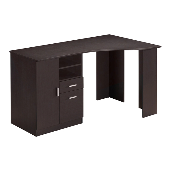
- Page 15 - Place both drawers and the Adjust Panel (G) into the cabinet as shown, then attach Hole Covers (3) DONE! Before you start using, please read all the warnings in the next page. Enjoy your new unit!
- Page 16 40Kg (90 Lbs) 4.5Kg (19 Lbs) 4.5Kg (10 Lbs) 4.5Kg (10 Lbs) 4.5Kg (10 Lbs) 4.5Kg (10 Lbs) Do not exceed the weight limits. Do not expose the surfaces to direct sunlight or to extreme environmental conditions. Clean the surfaces preferable with a soft cloth damped with a solution of mild soap and water, then dry with a clean towel.
Need help?
Do you have a question about the Techni Mobili RTA-8408 and is the answer not in the manual?
Questions and answers