
Related Manuals for Flight Model Katana-100CC


Summary of Contents for Flight Model Katana-100CC
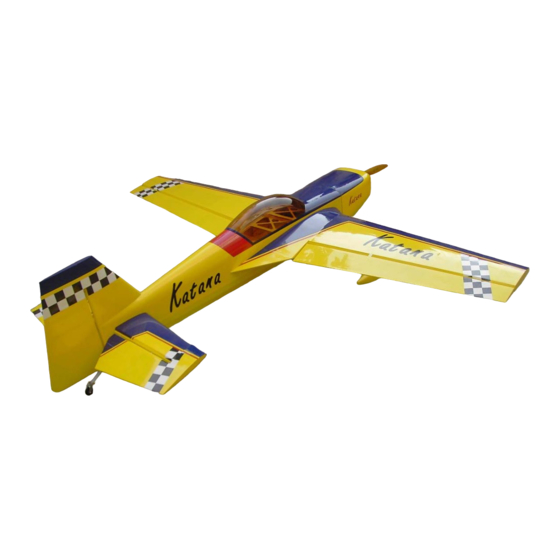
- Page 1 Caution:this plane is not a toy! Before use ,please carefully read this manual. Wing Span:106.1in/2695mm; Flying Weight:11700-12700g; Wing Area:136sq.dm; Radio:6channels 9servos; Length:93.3in/2370mm; Engine:100CC GAS;...
- Page 2 Cut away covering film for the servo. Attach the aileron to the main wing with AB glue. Screw the servo to the wing. Put the servo extension through the wing and pull through the wing root rib.
- Page 3 Assemble 2 aileron servo . Link the servo and tri-horns with pushrod and straper. Find out the holes on each sides and cut off the film of fuselage. Connect the main wings and the fuselage with joiner. Also pull the extension into the fuselage.
- Page 4 Use 4 nylon screws of each sides to ensure the wings fixed upto the fuselage. Glue wing tip by AB glue. Fix up the wheel to the screw by two collars.
- Page 5 Screw the wheel to the landing gear. Be assured that the screw is fixed up. Install the wheel cover, and fix it up to landing gear with two TP screws. Bolt landing gear strut to fuse with 4 bolts and washers.Ensure tapered edge of the gear strut is facing toward the rear.
- Page 6 Measure the right position and remove the film from the stabilizer. Glue the stablilizer to the fuselage. Connect the aileron and the stabilizer by hinges, and glue them.
- Page 7 Connect the rudder to the fuselage by hinges by AB glue. Install elevator servo. Insert rudder cable through the brass swage tube,then through the threaded coupler hole,and back through the brass swage tube as shown.
- Page 8 Loop the cable back through the brass swage tube as shown. Attach a metal threaded RC link to each threaded coupler.Attach the RC links to the rudder servo arm and then attach the servo arm to the rudder servo as shown. Fix the tri-horns to the fuselage as shown.
- Page 9 Attach straper to rudder control horn on both sides of the rudder. Attach the tail wheel to the tail landing gear as shown. Mount the tail wheel struts and springs using four TP screws.
- Page 10 Mount the tail wheel steering tiller using two TP screws. Attach the steering springs on both sides of the tail wheel to the rudder tiller and tail wheel tiller. Center the springs between both tillers. Drill the engine mounting holes as the board provided.
- Page 11 Assemble engine as shown. Make sure tighten firmly. Install inner muffler.
- Page 12 Assemble fuel tank. Fasten the fuel tank with nylon zipper provided. Completed picture as shown.
- Page 13 Assemble movable canopy which provide more convinient for assembling. 4 screw provided to lock canopy. Install electric equipment. Install the cowling with four TP screws.
- Page 14 Balance test A=A1 B=B1...
- Page 15 CONTROL THROWS & CG POSTION...
- Page 16 FINISHED PHOTO...
Need help?
Do you have a question about the Katana-100CC and is the answer not in the manual?
Questions and answers