Table of Contents
Advertisement
Quick Links
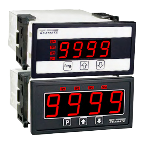
4 Digit 0.56" or 0.8" LEDs
in a 1/8 DIN CASE
General Features
• External transmitters or signal conditioners can be eliminat-
ed by direct connection of the sensor output to :
- DCA
ID02 : DC mV ±20mV, ±50mV, ±100mV, ±200mV w/24V Exc.
- DCV
ID01 : DC-Volts 2V/20V/200V w/24V Exc.
ID05 : DC-Volts 2V/20V/200V w/24V Exc. and Zero offset
adjustable pot
• Optional isolated 14 bit analog output. User or factory scalable
to 4 to 20 mA, 0 to 20 mA or 0 to 10 V across any desired
digital span from ± one count to the full scale range of - 1999
to 9999 (12000 counts).
• Optional Isolated Modbus RTU RS-485 serial communication
with selectable baud rate (9600, 19200), address and parity.
• Auto-sensing AC/DC power supply. For voltages between
85-265 VAC / 95-300 VDC (PS1) or 15-48 VAC / 10-72 VDC (PS2).
• Standard red or optional green or super bright red 4-digit LED
with display range -1999 to 9999 (12000 counts).
• Red or green 0.8" LED large display option
• Four annunciator LEDs provide front panel alarm status
indication for up to four setpoints.
• Up to optional six relays in combination of six, four or two 4
Amp Form A relays or two 9 Amp Form C with two or four 4
Amp Form A relays are available.
• Automatic intelligent averaging smooths noisy signals, while
providing a fast display response to real input signal changes.
• Three-button programming from the front panel
(UP, DOWN and PROGRAM buttons).
Software Features
• Front panel selectable four-level brightness control for digital
display and setpoint LEDs.
• Four programmable setpoints.
• Relay activation can be selected to occur above (HI) or below
(LO) each setpoint.
• Hysteresis setting for all four setpoints. Delay on make and
delay on break for SP1 and SP2.
• Peak and Valley. View and Reset.
• Program Lock switch
Auto Calibration Mode . . . . . . . . . . . . 5
Auto Calibration Procedure . . . . . . . . 5
Case Dimensions . . . . . . . . . . . . . . . 13
Connector Pinouts . . . . . . . . . . . 10-11
Controls and Indicators . . . . . . . . . . . 2
Component Layout. . . . . . . . . . . . . . 12
DL-40JANUS-DCA/DCV manual (d0114)
LEOPARD FAMILY
Range Output. . . . . . . . . . . . . . . . . . . 6
General Features . . . . . . . . . . . . . . . . 1
Installation Guideline . . . . . . . . . . . . 11
Texmate, Inc. Tel. (760) 598-9899 • www.texmate.com
DL-40JANUS-DCA
20/50/100/200mV DC Full Scale
DL-40JANUS-DCV
2/20/200V DC Meter
Two scaling methods - MANUAL (no external sig-
nal source required) and AUTO (requied an exter-
nal signal source). Optional Modbus RS-485 serial,
analog and up to six relays output.
DC Amp or DC Volt Meter, Transmitter and Controller
Specifications
Input Specs: ..............Depends on Input signal conditioner
A/D Converter: ..........14 bit single slope
Accuracy: ..................±(0.05% of reading + 2 counts)
Temp. Coeff.: .............100 ppm/°C (Typical)
Warm up time: ...........2 minutes
Conversion Rate: ......5 conversions per second (Typical)
Display: ......................4 digit 0.56" Red LED display (std),
Polarity: .....................Assumed positive. Displays - negative
Decimal Selection: ....Front panel button selectable, X•X•X•X•
Positive Overrange: ..Top segments of digital display flash
Negative Overrange: .Bottom segments of digital display flash
Relay Output: ............Up to Six Relays in combination of six,
Analog Output: .........Isolated 16 bit user scalable mA or V
AIC (mA out) ...........4-20 mA @ 0 to 500Ω max loop resistance
AIV (volts out) .......... 0-10 V DC @ 500 Ω or higher resistance
Power Supply: ...........AC/DC Auto sensing wide range supply
PS1 (std) ................85-265 VAC / 95-300 VDC, 50-400Hz @ 3W
PS2 .........................15-48 VAC / 10-72 VDC, 50-400Hz @ 2.5W
Operating Temp.: ......0 to 50 °C
Storage Temp: ...........-20 °C to 70 °C.
Relative Humidity: ....95% (non condensing)
Case Dimensions: ....1/8 DIN, Bezel: 96x48 mm (3.78"x1.89")
Weight: .......................6.5 oz., 8.5 oz when packed
Certification ...............UL Listed.
Index
Manual Rescaling. . . . . . . . . . . . . . . . 4
Manual Rescaling Procedure. . . . . . . 4
Meter Assembly . . . . . . . . . . . . . . . . 10
Modbus RTU Implementation . . . . . . 7
0.56" Green, 0.8" Red/Green, or
0.56" Super Bright Red are optional.
Range 0 to 9999 counts.
four or two 4 Amp Form A relays or two
9 Amp Form C with two or four 4 Amp
Form A relays.
Depth behind bezel: 117 mm (4.61")
Plus 11.8 mm (0.47") for Right-angled
connectors, or plus 20 mm (0.79") for
Straight-thru connector.
Ordering Information . . . . . . . . . . . . 15
Software Features . . . . . . . . . . . . . . . 1
Software Logic Tree . . . . . . . . . . . . . . 3
Specifications . . . . . . . . . . . . . . . . . . . 1
Setting and Calibration. . . . . . . . . . . . 6
Page 1
Advertisement
Table of Contents

Subscribe to Our Youtube Channel
Related Manuals for Texmate DL-40JANUS-DCA


Summary of Contents for Texmate DL-40JANUS-DCA
-
Page 1: Table Of Contents
Two Point Analog Output Range Installation Guideline ... . 11 Modbus Address for DL-40 Registers 8 Setting and Calibration... . 6 DL-40JANUS-DCA/DCV manual (d0114) Texmate, Inc. Tel. (760) 598-9899 • www.texmate.com Page 1... -
Page 2: Controls And Indicators
When a number is shown it indicates omitted or bypassed when the related hard- the initial factory default setting or a specific ware is not present “example number”. Page 2 Texmate, Inc. Tel. (760) 598-9899 • www.texmate.com DL-40JANUS-DCA/DCV manual (d0114) -
Page 3: Software Logic Tree
(L) Low the relay energizes below the setpoint. Setpoint are indicated [LHLH] from left to right SP1, SP2, SP3, SP4 [HLHL] confirm [HHHH] DL-40JANUS-DCA/DCV manual (d0114) Texmate, Inc. Tel. (760) 598-9899 • www.texmate.com Page 3... -
Page 4: Lens Cover & Metal Surround Case 14 Manual Rescaling
The menu branches to the DECIMAL POINT AND BRIGHTNESS SE See Page 6 LECTION, (see page6) and the display flashes [dP] and the previous decimal point selection. Decimal Point (dp) Page 4 Texmate, Inc. Tel. (760) 598-9899 • www.texmate.com DL-40JANUS-DCA/DCV manual (d0114) -
Page 5: Auto Calibration Mode
(positive and negative values are allowed). Decimal Point 2) The scaling requirement exceeded the capability of the meter (dp) (–1999 to 9999). 3) No input signal present, or incorrect connections. DL-40JANUS-DCA/DCV manual (d0114) Texmate, Inc. Tel. (760) 598-9899 • www.texmate.com Page 5... -
Page 6: Digital Span Selection For Analog Range Output
16 bit D to A to increment in stair case steps. Page 6 Texmate, Inc. Tel. (760) 598-9899 • www.texmate.com DL-40JANUS-DCA/DCV manual (d0114) -
Page 7: Modbus Rtu & Rs-485 Settings
ZERO value may return a value of 0xFFFE (-2). These registers have no meaning in Manual Rescaling Mode). DL-40JANUS-DCA/DCV manual (d0114) Texmate, Inc. Tel. (760) 598-9899 • www.texmate.com Page 7... -
Page 8: Modbus Address For Dl-40 Registers
Auto Mode, has no meaning in Manual mode 40031 0x001E UINT16 ISPAN Calibrated “span” measurement for displayed maximum input SPAN in Auto Mode, has no meaning in Manual mode Page 8 Texmate, Inc. Tel. (760) 598-9899 • www.texmate.com DL-40JANUS-DCA/DCV manual (d0114) -
Page 9: Setpoint & Relay Configuration Mode
STEP N Relays Activation [rLYS] The meter exits the setpoint mode and returns to the operational display. The Setpoint Relay programming mode is now complete. [LHLH] [HLHL] Confirm [HHHH] DL-40JANUS-DCA/DCV manual (d0114) Texmate, Inc. Tel. (760) 598-9899 • www.texmate.com Page 9... -
Page 10: Connector Pinouts
85-265 V AC / 95-370 V DC (PS1) or 18-48 V AC / 10-72 V DC (PS2). Component Layout Meter Assembly Standard plug-in screw terminal connectors provided by Texmate: Input Signal – Pins 1 to 6 Pins 1 to 6 are reserved for the input signal conditioner. -
Page 11: Installation Guideline
Shielding cables for input/output leads is 8. Recommended torque on all terminal plug screws is recommended with shield connection to earth ground 4.5 lb-in (0.51 N-m). near the meter preferred. DL-40JANUS-DCA/DCV manual (d0114) Texmate, Inc. Tel. (760) 598-9899 • www.texmate.com Page 11... -
Page 12: Component Layout
< Decrease Span Increase > SPAN Zero Offset ZERO Range Header PIN 3 (ID05) PIN 2 DC VOLTS Exc. On/Off PIN 1 Input Range 24V Exc Header Header Page 12 Texmate, Inc. Tel. (760) 598-9899 • www.texmate.com DL-40JANUS-DCA/DCV manual (d0114) -
Page 13: Case Dimensions
(96x96mm) or 4 up in Slide Clips can be ordered and doubled up Connector P/N:(OP-MTLCLIP) Catch DIN Cutout Spacer 1/2 DIN (96X192mm). Opening one behind the other. P/N: (75-DMTCLIPF) Socket DL-40JANUS-DCA/DCV manual (d0114) Texmate, Inc. Tel. (760) 598-9899 • www.texmate.com Page 13... - Page 14 The Metal Surround Case must be to be easily connected to the panel ground. factory installed on the polycarbonate case and once installed, it cannot be removed in the field. Page 14 Texmate, Inc. Tel. (760) 598-9899 • www.texmate.com DL-40JANUS-DCA/DCV manual (d0114)
-
Page 15: Ordering Information
Please see our website, www.texmate.com to configure a meter and see current pricing. BASIC MODEL NUMBER DL-40JANUS-DCA..96x48, Leopard, 4 Digit, DC Amps....RELAY OUTPUT DL-40JANUS-DCV .
Need help?
Do you have a question about the DL-40JANUS-DCA and is the answer not in the manual?
Questions and answers