Table of Contents
Advertisement
Quick Links
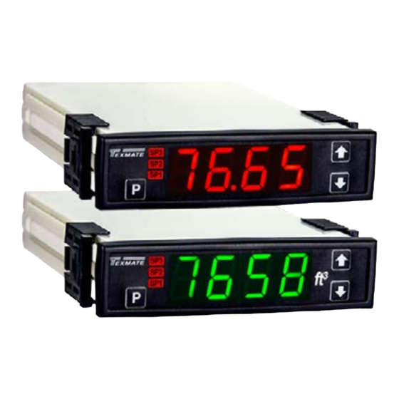
4 Digit 0.56" LEDs in a 1/16 DIN Case
Built-in Programmable Scale Factor
No Input required to calibrate
General Features
•
External transmitters or signal conditioners can be elimi-
nated by direct connection of the sensor or DCmV shunt
output to :
- DCA
ID02 : DC mV ±20mV, ±50mV, ±100mV, ±200mV w/24V Exc.
- DCV
ID01 : DC-Volts 2V/20V/200V w/24V Exc.
ID05 : DC-Volts 2V/20V/200V w/24V Exc. and Zero offset
adjustable pot
•
Optional isolated 16 bit analog output. User or factory
scalable to 4 to 20 mA, 0 to 20 mA or 0 to 10 V across
any desired digital span from ± one count to the full scale
range of 0 to 9999�
•
Auto-sensing AC/DC power supply. For voltages between
85-265 V AC / 95-300 V DC (PS1) or 15-48 V AC / 10-72
V DC (PS2)�
•
Standard red or optional green or super bright red 4-digit
LED with display range 0 to 9999.
•
Three annunciator LEDs provide front panel alarm status
indication for up to three setpoints�
•
One 9 Amp Form C and one 4 Amp Form A relays, or up to
three 4 Amp Form A relays are available�
•
Automatic intelligent averaging smooths noisy signals,
while providing a fast display response to real input signal
changes�
Software Features
• Three-button programming from the front panel
(UP, DOWN and PROGRAM buttons)�
• Front panel selectable four-level brightness control of digital dis-
play�
• Three programmable setpoints�
• Relay activation can be selected to occur above (HI) or below
(LO) each setpoint�
• Hysteresis setting for all three setpoints. Delay on make and
delay on break for SP1 and SP2�
• Peak and Valley. View and Reset.
Case Dimensions � � � � � � � � � � � � � � � � 9
Component Layout � � � � � � � � � � � � � � � 8
Connector Pinouts � � � � � � � � � � � � � � � 7
Connectors � � � � � � � � � � � � � � � � � � � � � 7
Controls and Indicators � � � � � � � � � � � 2
BL-40PSF-DCA _ BL-40PSF-DCV manual (d0082)
LEOPARD FAMILY
Digital Rescaling� � � � � � � � � � � � � � � � � 4
Digital Rescaling Procedure � � � � � � � � 4
Analog Range Output� � � � � � � � � � � � � 5
General Features � � � � � � � � � � � � � � � � 1
Texmate, Inc. Tel. (760) 598-9899 • www.texmate.com
BL-40PSF-DCA
20/50/100/200mV DC Full Scale
BL-40PSF-DCV
2/20/200V DC Meter
DC Amp or DC Volt Meter, Transmitter and Controller
with optional 4-20mA or 0-10 VDC Output.
Specifications
Input Specs: ��������������Single-ended, however isolated power
A/D Converter: ����������14 bit single slope
Accuracy: ������������������±(0�05% of reading + 2 counts)
Temp. Coeff�: �������������100 ppm/°C (Typical)
Warm up time: �����������2 minutes
Conversion Rate: ������5 conversions per second (Typical)
Display: ����������������������4 digit 0.56" Red LED display (std),
Polarity: ���������������������Assumed positive� Displays - negative
Decimal Selection: ����Front panel button selectable, X•X•X•X•
Positive Overrange: ��Top segments of digital display flash
Negative Overrange: Bottom segments of digital display flash
Relay Output: ������������Three 4 Amp Form A relays or one 9 Amp
Analog Output: ���������Isolated 16 bit user scalable mA or V
OIC (mA out) �����������4-20 mA @ 0 to 500٠max loop resistance
OIV (volts out) ���������� 0-10 V DC @ 500 ٠or higher resistance
Power Supply: �����������AC/DC Auto sensing wide range supply
PS1 (std) ����������������85-265 VAC / 95-300 VDC @ 2.5W max 3.2W
PS2 �������������������������15-48 VAC / 10-72 VDC @ 2�5W max 3�2W
Operating Temp�: ������0 to 50 °C
Storage Temp: �����������-20 °C to 70 °C�
Relative Humidity: ����95% (non condensing)
Case Dimensions: ����1/16 DIN Bezel 96x24mm
Weight: �����������������������7 oz, 9 oz when packed
Index
Input Module Compatibility � � � � � � � � � 1
Input Module Component Glossary � � � 9
Installation Guideline � � � � � � � � � � � � � 7
Ordering Information � � � � � � � � � � � � 10
Pin Descriptions � � � � � � � � � � � � � � � � � 7
supply enables differential measurements
up to a maximum common mode of 50V�
0�56" Green or Super Bright Red are
optional� Range 0 to 9999 counts�
Form C, and one 4 Amp Form A relay�
Depth behind bezel 122�2mm (4�83")
Plus 12�7mm (0�5") for Right-angled
connectors
Mode � � � � � � � � � � � � � � � � � � � � � � � � � � 6
Software Features � � � � � � � � � � � � � � � 1
Software Logic Tree � � � � � � � � � � � � � � 3
Specifications � � � � � � � � � � � � � � � � � � � 1
Range Setting & Calibration� � � � � � � � 5
Page 1
Advertisement
Table of Contents

Subscribe to Our Youtube Channel
Related Manuals for Texmate BL-40PSF-DCA


Summary of Contents for Texmate BL-40PSF-DCA
-
Page 1: Table Of Contents
Glossary of Programming Symbols � � 2 Two Point Analog Output Decimal Point & Brightness Selection � � 5 Range Setting & Calibration� � � � � � � � 5 BL-40PSF-DCA _ BL-40PSF-DCV manual (d0082) Texmate, Inc. Tel. (760) 598-9899 • www.texmate.com Page 1... -
Page 2: Controls And Indicators
When a number is shown it indi- omitted or bypassed when the related hard- cates the initial factory default setting or a ware is not present specific “example number”� Page 2 Texmate, Inc. Tel. (760) 598-9899 • www.texmate.com BL-40PSF-DCA _ BL-40PSF-DCV manual (d0082) -
Page 3: Software Logic Tree
Software Logic Tree The BL-40PSF-DCA and BL-40PSF-DCV are intelligent meters After the meter has been powered up, the four digits light up for with a hierarchical software structure designed for easy program- three seconds and then settle to the operational display indicating ming and operation, as shown below in the software logic tree�... -
Page 4: Digital Rescaling
Digital Rescaling The BL-40PSF-DCA and BL-40PSF-DCV meter may be rescaled without applying an external signal by changing the Offset and Scale factor� Offset is the reading that the meter will display for a zero input� The Offset may be set to any value from -1999 to +9999� The default value of the Offset is 000 Scale factor is the gain of the meter�... -
Page 5: Decimal Point & Brightness Selection
16 bit D to A to increment in stair case steps� BL-40PSF-DCA _ BL-40PSF-DCV manual (d0082) Texmate, Inc. Tel. (760) 598-9899 • www.texmate.com Page 5... -
Page 6: Setpoint Setting & Relay Configuration Mode
The meter exits the setpoint mode and returns to the operational display� SP1 and SP2 STEP N Relays The Setpoint Relay programming mode is now complete. Activation [rLYS] [LhL-] [hLh-] [hhh-] Page 6 Texmate, Inc. Tel. (760) 598-9899 • www.texmate.com BL-40PSF-DCA _ BL-40PSF-DCV manual (d0082) -
Page 7: Connector Pinouts
4� A circuit breaker or disconnect switch is required to disconnect power to the meter� The breaker/switch should be in close proximity to the meter and marked BL-40PSF-DCA _ BL-40PSF-DCV manual (d0082) Texmate, Inc. Tel. (760) 598-9899 • www.texmate.com Page 7... -
Page 8: Component Layout
This heder disable any programing function� To access the header, you must remove meter from case� Please see "Connector Pinouts" on page 7 for the instruction� Page 8 Texmate, Inc. Tel. (760) 598-9899 • www.texmate.com BL-40PSF-DCA _ BL-40PSF-DCV manual (d0082) -
Page 9: Case Dimensions
1/16 DIN Connector Slide Clips can be ordered and doubled up Catch or 4 up in 1/4 DIN (96x96mm). cases P/N:(OP-N4/96x48) Sockets one behind the other. P/N:(75-DMT96X24) BL-40PSF-DCA _ BL-40PSF-DCV manual (d0082) Texmate, Inc. Tel. (760) 598-9899 • www.texmate.com Page 9... -
Page 10: Ordering Information
BASIC MODEL NUMBER BL-40PSF-DCA 96x24mm, Leopard, 4 Digit, DC Amps . . . . . . . . . . . . . . $110 BL-40PSF-DCV 96x24mm, Leopard, 4 Digit, DC Volts . . . . . . . . . . . . . . . $110 Standard Options for this Model Number Special Options and Accessories (OA’s)
Need help?
Do you have a question about the BL-40PSF-DCA and is the answer not in the manual?
Questions and answers