Table of Contents
Advertisement
Quick Links
Large display option
0.8" red or green LED
General Features
•
External transmitters or signal conditioners can be eliminated
by direct connection of the sensor output to more than
38 Plug-in Input Signal Conditioners that include:
– AC/DC Current
– Pressure
– AC/DC Voltage
– Process
– Load Cell
– Prototype
*See models DL-40H for higher accuracy digitally linearized
thermocouple and RTD
•
Optional isolated 16 bit analog output. User or factory scalable
to 4 to 20 mA, 0 to 20 mA or 0 to 10 V across any desired
digital span from ± one count to the full scale range of – 1999
to 9999 (12000 counts).
•
Auto-sensing AC/DC power supply. For voltages between
85-265 V AC / 95-370 V DC (PS1) or 15-48 V AC / 10-72 V DC (PS2).
•
24 V DC excitation is available to power external transmitters
and 5 or 10 V DC excitation is available for resistance bridge
type sensors such as Load Cells and Pressure Transducers.
•
Standard red or optional green or super bright red 4-digit LED
with display range –1999 to 9999 (12000 counts).
•
Red or green 0.8" LED large display option
•
Four annunciator LEDs provide front panel alarm status
indication for up to four setpoints.
•
Two 10 Amp Form C and two 5 Amp Form A relays, or
optionally four 5 Amp Form A relays are available.
•
Automatic intelligent averaging smooths noisy signals, while
providing a fast display response to real level changes.
Software Features
• Three-button programming from the front panel
(UP , DOWN and PROGRAM buttons).
• Three front panel selectable ranges.
• Front panel selectable four-level brightness control of digital dis-
play, and setpoint LEDs.
• Four programmable setpoints.
• Relay activation can be selected to occur above (HI) or below
(LO) each setpoint.
• Hysteresis setting for all four setpoints. Delay on make and
delay on break for SP1 and SP2.
• Peak and Valley. View and Reset.
Case Dimensions . . . . . . . . . . .14
Component Layout . . . . . . . . . .8-9
Connector Pinouts . . . . . . . . . .7-8
Controls and Indicators . . . . . . . .2
Decimal Point & Brightness
Selection . . . . . . . . . . . . . . . . . . .5
Digital Calibration Mode . . . . . . . .4
Digital Calibration Procedure . . . .4
7/31/03 DL-40 DS (DL6)
4 Digit 0.56" or 0.8" LEDs
LEOPARD FAMILY
An economically smart programmable meter relay
with isolated 4 to 20 mA retransmission or
control loop output capability for measurement
and control applications in a 96x48mm case.
– Resistance
– *Temperature
– 4 to 20 mA
Digital Span Selection for
Analog Range Output . . . . . . . . .5
Functional Diagram . . . . . . . . . . .7
General Features . . . . . . . . . . . . .1
Glossary of Prog. Symbols . . . . .2
Input Module Analog Cal. . . . .13-14
Input Module Comp. Glossary . . .13
Input Module Compatibility . . . . . .1
Texmate, Inc. Tel. (760) 598-9899 • www.texmate.com
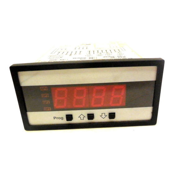
DL-40
Leopard Panel Meter
in a 1/8 DIN CASE
Input Module Compatibility
LEOPARD FAMILY: More than 38 different
Plug-in I-Series Input Signal Conditioners are
approved for Texmate's Leopard Family of meters.
Some examples are shown on pages 10 - 12.
See www.texmate.com for an up to date listing.
Specifications
Input Specs: ..............Depends on Input signal conditioner
A/D Converter: ..........14 bit single slope
Accuracy: ..................±(0.05% of reading + 2 counts)
Temp. Coeff.: ............100 ppm/°C (Typical)
Warm up time: ..........2 minutes
Conversion Rate: ......5 conversions per second (Typical)
Display:......................4 digit 0.56" Red LED display (std),
Polarity: ....................Assumed positive. Displays – negative
Decimal Selection:....Front panel button selectable, X•X•X•X•
Positive Overrange:..Top segments of digital display flash
Negative Overrange: Bottom segments of digital display flash
Relay Output: ............Two 5 Amp Form A relays and two 10
Analog Output: ........Isolated 16 bit user scalable mA or V
AIC (mA out) ..........4-20 mA @ 0 to 500Ω max loop resistance
AIV (volts out) ..........0-10 V DC @ 500 Ω or higher resistance
Power Supply: ..........AC/DC Auto sensing wide range supply
PS1 (std) ................85-265 VAC / 95-370 VDC @ 2.5W max 3.5W
PS2 ........................15-48 VAC / 10-72 VDC @ 2.5W max 3.5W
Operating Temp.: ......0 to 60 °C
Storage Temp: ..........–20 °C to 70 °C.
Relative Humidity: ....95% (non condensing)
Case Dimensions: ....1/8 DIN, Bezel: 96x48 mm (3.78"x1.89")
Weight: ......................6.5 oz., 8.5 oz when packed
Index
I-Series Input Signal
Conditioning Modules . . . . . . .10-12
Lens Cover . . . . . . . . . . . . . . . .15
Metal Surround Case . . . . . . . . .15
Ordering Information . . . . . . . . .16
Setpoint Setting & Relay
Configuration Mode . . . . . . . . . . .6
Software Features . . . . . . . . . . . .1
NOW FEATURING
OPTIONAL PLUG-IN
RELAY OR SSR
OUTPUT MODULES
0.56" or 0.8" Red, Green or Super
Bright Red (optn)
Range –1999 to 9999 counts.
Amp Form C, or 5 Amp form A relays.
Depth behind bezel: 117 mm (4.61")
Plus 11.8 mm (0.47") for Right-angled
connectors, or plus 20 mm (0.79") for
Straight-thru connector.
Software Logic Tree . . . . . . . . . . .3
Specifications . . . . . . . . . . . . . . .1
Two Point Analog Output
Range Setting and Calibration . . .5
LEOPARD
Page 1
Advertisement
Table of Contents

Subscribe to Our Youtube Channel
Related Manuals for Texmate DL-40


Summary of Contents for Texmate DL-40
-
Page 1: General Features
Some examples are shown on pages 10 - 12. – AC/DC Voltage – Process – *Temperature LEOPARD See www.texmate.com for an up to date listing. – Load Cell – Prototype – 4 to 20 mA *See models DL-40H for higher accuracy digitally linearized... -
Page 2: Controls And Indicators
When a number is shown it indicates omitted or bypassed when the related hard- the initial factory default setting or a specific ware is not present “example number”. Page 2 Texmate, Inc. Tel. (760) 598-9899 • www.texmate.com 7/31/03 DL-40 DS (DL6) -
Page 3: Software Logic Tree
Software Logic Tree The DL-40 is an intelligent meter with a hierarchical software After the meter has been powered up, the structure designed for easy programming and operation, as four digits light up for three seconds and then shown below in the software logic tree. -
Page 4: Digital Calibration Mode
(positive and negative values are allowed). 2) The scaling requirement exceeded the capability of the meter Decimal Point (–1999 to 9999). (dp) 3) No input signal present, or incorrect connections. Page 4 Texmate, Inc. Tel. (760) 598-9899 • www.texmate.com 7/31/03 DL-40 DS (DL6) -
Page 5: Decimal Point And Brightness Selection
16 bit D to A to increment in stair case steps. 7/31/03 DL-40 DS (DL6) Texmate, Inc. Tel. (760) 598-9899 • www.texmate.com Page 5... - Page 6 2) Press the button. [LhLh] The meter exits the setpoint mode and returns to the operational display. [hLhL] [hhhh] The Setpoint Relay programming mode is now complete. Page 6 Texmate, Inc. Tel. (760) 598-9899 • www.texmate.com 7/31/03 DL-40 DS (DL6)
- Page 7 10 Amp Form C and dual 5 Amp Form A relays. An analog output module is also shown as installed. Pin Socket Pin Socket Pin Socket The DL-40 uses plug-in type screw terminal connectors for all input Input Power Right-angled Straight-thru Screw Terminal Plug Screw Terminal Plug and output connections.
-
Page 8: Component Layout
Component Layout Component Layout Relay Relay Output Output Module Module Carrier Carrier Board Board Analog Analog Output Output Module Module Main Board Input Signal Input Signal Conditioner Conditioner Page 8 Texmate, Inc. Tel. (760) 598-9899 • www.texmate.com 7/31/03 DL-40 DS (DL6) - Page 9 High Volt Main Board Low Volt Main Board Low Voltage High Voltage Transformer is Transformer is Colored Black Colored Grey LOW VOLTS MODULE HIGH VOLTS MODULE Output Module Carrier Board 7/31/03 DL-40 DS (DL6) Texmate, Inc. Tel. (760) 598-9899 • www.texmate.com Page 9...
-
Page 10: I-Series Input Signal Conditioning Modules
Where appropriate, all the standard ranges shown are designed to be header selectable by the user, and Texmate's unique SPAN ADJUST Header facilitates scaling to almost any required engineering unit. - Page 11 < Decrease Zero Increase > PIN 2 250Ω +24 V LEOPARD LEOPARD IP07 IPO7 Fully User Scalable < Increase Span Decrease > < Decrease Span Increase > LYNX LYNX 7/31/03 DL-40 DS (DL6) Texmate, Inc. Tel. (760) 598-9899 • www.texmate.com Page 11...
- Page 12 User Selectable Accuracy ±0.05% + 2 digits. Power Supply 5 V or 10 V IT-11 RTD 100Ω Pt , 3/4 wire, °C/°F, 1°/0.1° resolution User Selectable Accuracy ±0.05% + 2 digits. Page 12 Texmate, Inc. Tel. (760) 598-9899 • www.texmate.com 7/31/03 DL-40 DS (DL6)
- Page 13 ZERO meter). Typically it enables the input signal to be Turn Clockwise to Texmate’s unique SPAN ADJUST and SPAN RANGE Headers pro- offset ±5% of full scale (-100 to +100 counts). Increase Reading vide the circuit equivalent of an ultra-precision one megohm 75 or –...
-
Page 14: Case Dimensions
10 mA which is (10÷16)=62.5% of the examples 16 mA signal span. Texmate’s unique ZERO OFFSET RANGE Header enables the use of a simple two step scaling and calibration procedure for those 2 To scale down the Signal Span to 62.5% select the (Hi Range) process signals that require large offsets. -
Page 15: Metal Surround Case Op-Mtl96X48
* Metal Surround Case must be factory installed. Metal Surround Case Meter with metal surround case and screw-type mounting clips assembled Ground Tab Screw-type Mounting Clip P/N: OP-MTLCLIP Metal Surround Case P/N: OP-MTL96X48 7/31/03 DL-40 DS (DL6) Texmate, Inc. Tel. (760) 598-9899 • www.texmate.com Page 15... -
Page 16: Ordering Information
However, since normal use and service for a period of one year from date of shipment. Texmate’s obligations we have no control over the use of our products once they are shipped, NO WARRANTY...
Need help?
Do you have a question about the DL-40 and is the answer not in the manual?
Questions and answers