Table of Contents
Advertisement
Quick Links
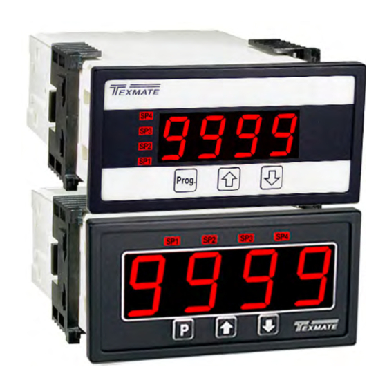
4 Digit 0.56" or 0.8" LEDs
in a 1/8 DIN CASE
General Features
• Optional isolated 14 bit analog output. User or factory scalable
to 4 to 20 mA, 0 to 20 mA or 0 to 10 V across any desired
digital span from ± one count to the full scale range of – 1999
to 9999 (12000 counts).
• Optional Isolated Modbus RTU RS-485 serial communication
with selectable baud rate (9600, 19200), address and parity.
• Auto-sensing AC/DC power supply. For voltages between
85-265 VAC / 95-300 VDC (PS1) or 15-48 VAC / 10-72 VDC (PS2).
• Standard red or optional green or super bright red 4-digit LED
with display range –1999 to 9999 (12000 counts).
• Red or green 0.8" LED large display option
• Four annunciator LEDs provide front panel alarm status
indication for up to four setpoints.
• Optional two 9 Amp Form C and two 4 Amp Form A relays, or
four 4 Amp Form A relays are available.
• Automatic intelligent averaging smooths noisy signals, while
providing a fast display response to real input signal changes.
• Three-button programming from the front panel
(UP, DOWN and PROGRAM buttons).
Software Features
• Front panel selectable four-level brightness control for digital
display and setpoint LEDs.
• Four programmable setpoints.
• Relay activation can be selected to occur above (HI) or below
(LO) each setpoint.
• Hysteresis setting for all four setpoints. Delay on make and
delay on break for SP1 and SP2.
• Peak and Valley. View and Reset.
• Program Lock switch
Auto Calibration Mode . . . . . . . . . . . . 5
Auto Calibration Procedure . . . . . . . . 5
Case Dimensions . . . . . . . . . . . . . . . 14
Connector Pinouts . . . . . . . . . . . 10-11
Controls and Indicators . . . . . . . . . . . 2
Component Layout. . . . . . . . . . . . . . 12
DL-40JANUS-DCA/DCV manual (d0114)
LEOPARD FAMILY
Digital Span Selection for Analog
Range Output. . . . . . . . . . . . . . . . . . . 6
Decimal Point & Brightness Selection. . 6
General Features . . . . . . . . . . . . . . . . 1
Glossary of Programming Symbols . . 2
Input Module Component Glossary . . 13
Installation Guideline . . . . . . . . . . . . 14
Texmate, Inc. Tel. (760) 598-9899 • www.texmate.com
DL-40JANUS-PROCESS
With two scaling methods- MANUAL
(requiring no signal source) and AUTO
(requiring an external signal source)
A powerful smart 4-20mA/0-10V
process
Meter, Transmitter and Controller with
al Modbus RS-485 serial, analog and relays output
Specifications
Input Specs: ��������������Depends on Input signal conditioner
A/D Converter: ����������14 bit single slope
Accuracy: ������������������±(0�05% of reading + 2 counts)
Temp. Coeff�: �������������100 ppm/°C (Typical)
Warm up time: �����������2 minutes
Conversion Rate: ������5 conversions per second (Typical)
Display: ����������������������4 digit 0.56" Red LED display (std),
Polarity: ���������������������Assumed positive� Displays – negative
Decimal Selection: ����Front panel button selectable, X•X•X•X•
Positive Overrange: ��Top segments of digital display flash
Negative Overrange: �Bottom segments of digital display flash
Relay Output: ������������Two 4 Amp Form A relays and two 9
Analog Output: ���������Isolated 16 bit user scalable mA or V
AIC (mA out) �����������4-20 mA @ 0 to 500٠max loop resistance
AIV (volts out) ���������� 0-10 V DC @ 500 ٠or higher resistance
Power Supply: �����������AC/DC Auto sensing wide range supply
PS1 (std) ����������������85-265 VAC / 95-300 VDC, 50-400Hz @ 3W
PS2 �������������������������15-48 VAC / 10-72 VDC, 50-400Hz @ 2�5W
Operating Temp�: ������0 to 50 °C
Storage Temp: �����������–20 °C to 70 °C�
Relative Humidity: ����95% (non condensing)
Case Dimensions: ����1/8 DIN, Bezel: 96x48 mm (3�78"x1�89")
Weight: �����������������������6�5 oz�, 8�5 oz when packed
Certification ���������������UL Listed�
Index
Lens Cover & Metal Surround Case 15
Manual Rescaling. . . . . . . . . . . . . . . . 4
Manual Rescaling Procedure. . . . . . . 4
Meter Assembly . . . . . . . . . . . . . . . . 10
Modbus RTU & RS-485 Settings . . . . 7
Modbus RTU Implementation . . . . . . 7
Modbus Address for DL-40 Registers 8
0�56" Green, 0�8" Red/Green, or
0�56" Super Bright Red are optional�
Range 0 to 9999 counts�
Amp Form C, or 4 Amp form A relays�
Depth behind bezel: 117 mm (4�61")
Plus 11�8 mm (0�47") for Right-angled
connectors, or plus 20 mm (0�79") for
Straight-thru connector�
Ordering Information . . . . . . . . . . . . 16
Setpoint & Relay Configuration Mode . . . .9
Software Features . . . . . . . . . . . . . . . 1
Software Logic Tree . . . . . . . . . . . . . . 3
Specifications . . . . . . . . . . . . . . . . . . . 1
Two Point Analog Output Range
Setting and Calibration. . . . . . . . . . . . 6
option-
.
Page 1
Advertisement
Table of Contents

Subscribe to Our Youtube Channel
Related Manuals for Texmate LEOPARD DL-40US-PROCESS


Summary of Contents for Texmate LEOPARD DL-40US-PROCESS
- Page 1 Two Point Analog Output Range Installation Guideline ... . 14 Modbus Address for DL-40 Registers 8 Setting and Calibration... . 6 DL-40JANUS-DCA/DCV manual (d0114) Texmate, Inc. Tel. (760) 598-9899 • www.texmate.com Page 1...
-
Page 2: Controls And Indicators
When a number is shown it indicates omitted or bypassed when the related hard- the initial factory default setting or a specific ware is not present “example number”� Page 2 Texmate, Inc. Tel. (760) 598-9899 • www.texmate.com DL-40JANUS-DCA/DCV manual (d0114) -
Page 3: Software Logic Tree
(L) Low the relay energizes below the setpoint. Setpoint are indicated [LHLH] from left to right SP1, SP2, SP3, SP4 [HLHL] confirm [HHHH] DL-40JANUS-DCA/DCV manual (d0114) Texmate, Inc. Tel. (760) 598-9899 • www.texmate.com Page 3... - Page 4 The menu branches to the DECIMAL POINT AND BRIGHTNESS SE See Page 6 LECTION, (see page6) and the display flashes [dP] and the previous decimal point selection� Decimal Point (dp) Page 4 Texmate, Inc. Tel. (760) 598-9899 • www.texmate.com DL-40JANUS-DCA/DCV manual (d0114)
-
Page 5: Auto Calibration Procedure
(positive and negative values are allowed)� Decimal Point 2) The scaling requirement exceeded the capability of the meter (dp) (–1999 to 9999)� 3) No input signal present, or incorrect connections� DL-40JANUS-DCA/DCV manual (d0114) Texmate, Inc. Tel. (760) 598-9899 • www.texmate.com Page 5... -
Page 6: Decimal Point And Brightness Selection
16 bit D to A to increment in stair case steps� Page 6 Texmate, Inc. Tel. (760) 598-9899 • www.texmate.com DL-40JANUS-DCA/DCV manual (d0114) - Page 7 ZERO value may return a value of 0xFFFE (-2)� These registers have no meaning in Manual Rescaling Mode)� DL-40JANUS-DCA/DCV manual (d0114) Texmate, Inc. Tel. (760) 598-9899 • www.texmate.com Page 7...
- Page 8 Auto Mode, has no meaning in Manual mode 40031 0x001E UINT16 ISPAN Calibrated “span” measurement for displayed maximum input SPAN in Auto Mode, has no meaning in Manual mode Page 8 Texmate, Inc. Tel. (760) 598-9899 • www.texmate.com DL-40JANUS-DCA/DCV manual (d0114)
- Page 9 STEP N Relays Activation [rLYS] The meter exits the setpoint mode and returns to the operational display� The Setpoint Relay programming mode is now complete. [LHLH] [HLHL] Confirm [HHHH] DL-40JANUS-DCA/DCV manual (d0114) Texmate, Inc. Tel. (760) 598-9899 • www.texmate.com Page 9...
-
Page 10: Connector Pinouts
85-265 V AC / 95-370 V DC (PS1) or 18-48 V AC / 10-72 V DC (PS2)� Component Layout Meter Assembly Standard plug-in screw terminal connectors provided by Texmate: Input Signal – Pins 1 to 6 Pins 1 to 6 are reserved for the input signal conditioner�... - Page 11 Relay Modules with 4 Independent 400V OR15 210mA DC only SSRs OR16 DL Series Order Code Options OR51 210mA OR52 210mA 210mA OR53 210mA 210mA 210mA OR54 210mA 210mA 210mA 210mA DL-40JANUS-DCA/DCV manual (d0114) Texmate, Inc. Tel. (760) 598-9899 • www.texmate.com Page 11...
-
Page 12: Component Layout
< Decrease Span Increase > SPAN Zero Offset ZERO Range Header PIN 3 PIN 2 DC VOLTS Exc� On/Off PIN 1 (ID05) Input Range 24V Exc Header Header Page 12 Texmate, Inc. Tel. (760) 598-9899 • www.texmate.com DL-40JANUS-DCA/DCV manual (d0114) -
Page 13: Input Module Component Glossary
80% 90% 100% – Equivalent Equivalent Circuit Circuit 75 Turn Potentiometer 75 Turn Potentiometer Acts like a 150 Turn Potentiometer Low Range High Range Input LO Input HI DL-40JANUS-DCA/DCV manual (d0114) Texmate, Inc. Tel. (760) 598-9899 • www.texmate.com Page 13... -
Page 14: Case Dimensions
The circuit breaker or wall switch must be rated for the applied voltage (e�g�, 120VAC or 240VAC) and current appropriate for the electrical application (e�g�, 15A or 20A)� Page 14 Texmate, Inc. Tel. (760) 598-9899 • www.texmate.com DL-40JANUS-DCA/DCV manual (d0114) -
Page 15: Clear Lockable Water-Proof Lens Cover Op-N4X/96X48
The Metal Surround Case must be to be easily connected to the panel ground� factory installed on the polycarbonate case and once installed, it cannot be removed in the field� DL-40JANUS-DCA/DCV manual (d0114) Texmate, Inc. Tel. (760) 598-9899 • www.texmate.com Page 15... -
Page 16: Ordering Information
However, since normal use and service for a period of one year from date of shipment. Texmate’s obligations we have no control over the use of our products once they are shipped, NO WARRANTY...
Need help?
Do you have a question about the LEOPARD DL-40US-PROCESS and is the answer not in the manual?
Questions and answers