Advertisement
E469078
General Features
• External transmitters or signal conditioners can be eliminated by
directly connecting the sensor to more than 33 I-Series Plug-in
Input Signal Conditioners that include:
- AC Current
- AC Voltage
- DC Current
- DC Voltage
- Load Cell
- Pressure
• Pre-calibrated I-Series Input Signal Conditioning
modules, that have span or zero potentiometers, can be
interchanged between any I-Series compatible meter,
without recalibration, because all of the analog scaling and
reference circuitry is self-contained within the module.
• 24 V DC excitation is available to power external
transmitters and 5 or 10 V DC excitation is available for
strain-gages, load cells and resistance bridge type sensors.
• AC/DC Auto-sensing power supply. For voltages between
85-265 V AC / 95-300 V DC (PS1) or 15-48 V AC / 10-72 V DC (PS2).
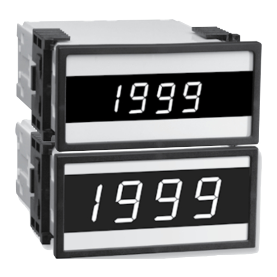
• Standard red or optional green or super bright red 3 1/2-digit
0.56" LED with display range -1999 to 1999 (4000 counts).
• Red or green 0.8" LED large display option.
• Display brightness may be externally controlled.
• 1/8 DIN (96 x 48mm ) case easily mounts in thin or thick
panels (up to 2'). May be ordered with optional extra fire
resistant metal case.
• Optional NEMA-4X, IP-65 hinged, lockable, water and dust
proof cover.
• UL Listed
Case Dimensions . . . . . . . . . . . . . . . . . . . . . . . . . . . . . . . . . . 7
Component Layout . . . . . . . . . . . . . . . . . . . . . . . . . . . . . . . . . 3
Connector Pinouts . . . . . . . . . . . . . . . . . . . . . . . . . . . . . . . . . 2
Connectors . . . . . . . . . . . . . . . . . . . . . . . . . . . . . . . . . . . . . . . 2
Functional Diagram . . . . . . . . . . . . . . . . . . . . . . . . . . . . . . . . 2
General Features . . . . . . . . . . . . . . . . . . . . . . . . . . . . . . . . . . 1
I-Series Input Signal Conditioning Modules. . . . . . . . . . . . 3-5
DX-35_UL DS (DX1_UL)
LYNX FAMILY
Large display option
0.8" red or green LED
display, for monitoring and measurement applications.
- Process
- Prototype
- Resistance
- Strain-gage
-Temperature
- 4 to 20 mA
3 1/2 DIGIT 0.56" or 0.8" LED
A versatile digital panel meter with standard or large
Input Module Compatibility
LYNX FAMILY: More than 33 different Plug-in
✔
I-Series Input Signal Conditioners are approved
for Texmate's Lynx Family of meters. As shown on
pages 3 to 5.
See www.texmate.com for an up to date listing.
Specifications
Input Specs: ..............Depends on input signal conditioner
A/D Converter: ..........12 bit dual slope
Accuracy: ..................±(0.05% of reading + 2 counts)
Temp. Coeff.: .............100 ppm/°C (Typical)
Warm up time: ...........2 minutes
Conversion Rate: ......3 conversions per second (Typical)
Display: ......................3 1/2 digit 0.56" Red LED display (std),
Polarity: .....................Assumed positive. Displays - negative
Decimal Selection: ....Header under face plate, X•X•X•X
Positive Overrange: ..1 (MSD) is displayed with all other
Negative Overrange: 1 (MSD) and - sign are displayed with
Power Supply: ...........AC/DC Auto sensing wide range supply
PS1 (std) ................85-265 VAC, 50-400Hz / 95-300 VDC @1.5W
PS2 .........................15-48 VAC,50-400Hz / 10-72 VDC @4.0W
Operating Temp.: ......0 to 50 °C
Storage Temp: ...........-20 °C to 70 °C.
Relative Humidity: ....95% (non condensing)
Case Dimensions: ....1/8 DIN, Bezel: 96x48 mm (3.78"x1.89")
Weight: .......................8 oz., 11 oz when packed.
Index
Input Module Calibration Procedures. . . . . . . . . . . . . . . . . 6-7
Input Module Compatibility . . . . . . . . . . . . . . . . . . . . . . . . . . . 1
Input Module Component Glossary . . . . . . . . . . . . . . . . . . . . 6
Installation Guidelines . . . . . . . . . . . . . . . . . . . . . . . . . . . . . . 8
Ordering Information . . . . . . . . . . . . . . . . . . . . . . . . . . . . . . . 8
Pin Descriptions . . . . . . . . . . . . . . . . . . . . . . . . . . . . . . . . . . . 2
Specifications . . . . . . . . . . . . . . . . . . . . . . . . . . . . . . . . . . . . . 1
DX-35
Lynx Panel Meter
in a 1/8 DIN Case
0.56" or 0.8" Green or Super Bright
Red (optn). Range -1999 to 1999 counts.
digits blank.
all other digits blank.
Depth behind bezel: 117 mm (4.61")
Plus 11.8 mm (0.47") for Right-angled
connector or plus 20 mm (0.79") for
Straight-thru connector.
LYNX
Page 1
Advertisement
Table of Contents

Subscribe to Our Youtube Channel
Related Manuals for Texmate DX-35-XX-PS1


Summary of Contents for Texmate DX-35-XX-PS1
-
Page 1: Table Of Contents
Input Signal Conditioners that include: for Texmate’s Lynx Family of meters. As shown on – AC Current – Process pages 3 to 5. – AC Voltage – Prototype LYNX See www.texmate.com for an up to date listing. – DC Current – Resistance – DC Voltage – Strain-gage Specifications – Load Cell –Temperature Input Specs: ....Depends on input signal conditioner... -
Page 2: Functional Diagram
Pins 9, K - Decimal XX.XX: Connect to pin 6 or pin F to activate Pin 12 - Dim/Blank: When this pin is connected to the Common decimal XX.XX. Pin 11 the display is blanked out. If it is connected through an external 1KΩ pot, the display may be dimmed. Pins 10, L - Decimal X.XXX: Connect to pin 6 or pin F to activate decimal X.XXX. Page 2 Texmate, Inc. Tel. (760) 598-9899 • www.texmate.com DX-35_UL DS (DX1_UL) -
Page 3: I-Series Input Signal Conditioning Modules
Where appropriate, all the standard ranges shown are designed to be header selectable by the user, and Texmate's unique SPAN ADJUST Header facilitates scaling to almost any required engineering unit. See Input Module Component Glossary and Calibration on pages 6 and 8. Unless otherwise specified Texmate will ship all modules precalibrated with factory preselected ranges and/or scalings as shown in BOLD type. Other precalibrated standard ranges or custom ranges may be ordered. Factory installed custom scaling and other custom options are also available (see Ordering Information, Special Options on last page). - Page 4 IF02: Line Frequency 090D 269D 24V Exc TIGER TIGER IP07 IF06 100 to 140VAC LEOPARD LEOPARD IP07 Frequency to Voltage Conversion ZERO SPAN < Increase Span Decrease > LYNX LYNX Page 4 Texmate, Inc. Tel. (760) 598-9899 • www.texmate.com DX-35_UL DS (DX1_UL)
- Page 5 J ±(2 °C + 1 digit) typical J ±(4 °F + 1 digit) maximum ZERO LYNX K ±(3°C + 1 digit) typical SPAN K ±(5 °F + 1 digit) maximum LYNX DX-35_UL DS (DX1_UL) Texmate, Inc. Tel. (760) 598-9899 • www.texmate.com Page 5...
-
Page 6: Input Module Calibration Procedures
100 Counts 100 Counts or 150 turn potentiometer that can infinitely scale down any Input Signal SPAN to provide any full scale Digital Display Span from 15 Turn Potentiometer Page 6 Texmate, Inc. Tel. (760) 598-9899 • www.texmate.com DX-35_UL DS (DX1_UL) - Page 7 10 mA which is (10÷16)=62.5% of the examples 16 mA signal span. 2 To scale down the Signal Span to 62.5% select the (Hi Range) Texmate’s unique ZERO OFFSET RANGE Header enables the use of a simple two step scaling and calibration procedure for those Position on the Span Range Header and the 70% Signal Span position on the SPAN ADJUST Header (position 2).
-
Page 8: Installation Guidelines
6. See Connector Pinouts section for wiring. 7. Use 28-12 AWG wiring, minimum 90˚C (HH) tem- perature rating. Strip wire approximately 0.3 in. (7-8 mm). 8. Recommended torque on all terminal plug screws is 4.5 lb-in (0.51 N-m). Page 8 Texmate, Inc. Tel. (760) 598-9899 • www.texmate.com DX-35_UL DS (DX1_UL) -
Page 9: Ordering Information
Texmate. satisfaction of Texmate to be thus defective. The warranty shall not apply to any equipment...
Need help?
Do you have a question about the DX-35-XX-PS1 and is the answer not in the manual?
Questions and answers