Advertisement
Quick Links
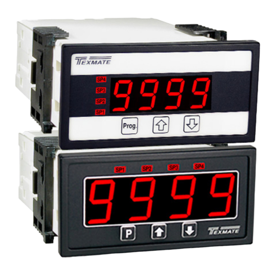
0.56" or optional 0.8" large display red or green LED
General Features
• External transmitters or signal conditioners can be eliminated
by direct connection of the sensor output to more than 29 Plug-
in Input Signal Conditioners that include:
– AC Current
– Pressure
– AC/DC Voltage
– Process
– Load Cell
– Prototype
*See models DL-40-RTD and DL-40-RTD for higher accuracy
digitally linearized thermocouple and RTD
• Optional isolated 14 bit analog output. User or factory scalable
to 4 to 20 mA, 0 to 20 mA or 0 to 10 V across any desired
digital span from ± one count to the full scale range of – 1999
to 9999 (12000 counts).
• Optional Isolated Modbus RTU RS-485 serial communication
with selectable baud rate (9600, 19200), address and parity.
• Auto-sensing AC/DC power supply. For voltages between
85-265 VAC / 95-370 VDC (PS1) or 15-48 VAC / 10-72 VDC (PS2).
• 24 V DC excitation is available to power external transmitters
and 5 or 10 V DC excitation is available for resistance bridge
type sensors such as Load Cells and Pressure Transducers.
• Standard red or optional green or super bright red 4-digit LED
with display range –1999 to 9999 (12000 counts).
• Red or green 0.8" LED large display option
• Four annunciator LEDs provide front panel alarm status
indication for up to four setpoints.
• Optional two 9 Amp Form C and two 4 Amp Form A relays, or
four 4 Amp Form A relays are available.
• Automatic intelligent averaging smooths noisy signals, while
providing a fast display response to real input signal changes.
• Three-button programming from the front panel
(UP, DOWN and PROGRAM buttons).
Software Features
• Front panel selectable four-level brightness control of digital dis-
play, and setpoint LEDs.
• Four programmable setpoints.
• Relay activation can be selected to occur above (HI) or below
(LO) each setpoint.
• Hysteresis setting for all four setpoints. Delay on make and
delay on break for SP1 and SP2.
• Peak and Valley. View and Reset.
Auto Calibration Mode . . . . . . . . . . . . 5
Auto Calibration Procedure . . . . . . . . 5
Case Dimensions . . . . . . . . . . . . . . . 16
Connector Pinouts . . . . . . . . . . . 10-11
Controls and Indicators . . . . . . . . . . . 2
Digital Span Selection for Analog
Range Output. . . . . . . . . . . . . . . . . . . 6
DL-40JANUS manual (d0111)
LEOPARD FAMILY
– Resistance
– *Temperature
– 4 to 20 mA
Decimal Point & Brightness Selection. . 6
General Features . . . . . . . . . . . . . . . . 1
Glossary of Programming Symbols . . 2
Input Module Analog Calibration . . . . 15
Input Module Component Glossary 1 4-15
Input Module Calibration . . . . . . 15-16
Input Signal Conditioning Modules . 12-14
Texmate, Inc. Tel. (760) 598-9899 • www.texmate.com
DL-40JANUS
With or without an External Signal
Source for Rescaling
A powerful, smart, programmable panel meter
with optional Modbus RS-485 serial, analog and
relays output for measurement and control
applications in a 1/8 DIN 96x48mm case.
Input Module Compatibility
LEOPARD FAMILY: More than 29 different
Plug-in I-Series Input Signal Conditioners are
approved for Texmate's Leopard Family of meters.
Some examples are shown on pages 12 - 14.
See www.texmate.com for an up to date listing.
Specifications
Input Specs: ................Depends on Input signal conditioner
A/D Converter: . ............14 bit single slope
Accuracy: . ....................±(0.05% of reading + 2 counts)
Temp. Coeff.: ...............100 ppm/°C (Typical)
Warm up time: .............2 minutes
Conversion Rate: . ........5 conversions per second (Typical)
Display: . .......................4 digit 0.56" Red LED display (std), 0.56"
Range –1999 to 9999 counts.
Polarity: . .......................Assumed positive. Displays – negative
Decimal Selection: . ......Front panel button selectable, X•X•X•X•
Positive Overrange: . ....Top segments of digital display flash
Negative Overrange: ...Bottom segments of digital display flash
Relay Output: ..............Two 4 Amp Form A relays and two 9
Analog Output: ............Isolated 14 bit user scalable mA or V
AIC (mA out) . ............... 4 -20 mA @ 0 to 500Ω max loop resis-
AIV (volts out) .............. 0 -10 V DC @ 500 Ω or higher resistance
Power Supply: .............AC/DC Auto sensing wide range supply
PS1 (std) . .................... 8 5-265 VAC / 95-370 VDC @ 3W max
PS2 .............................. 1 5-48 VAC / 10-72 VDC @ 2.5W max
Operating Temp.: .........0 to 60 °C
Storage Temp: .............–20 °C to 70 °C.
Relative Humidity: .......95% (non condensing)
Case Dimensions: .......1/8 DIN, Bezel: 96x48 mm (3.78"x1.89")
Plus 11.8 mm (0.47") for Right-angled
Weight: ........................6.5 oz., 8.5 oz when packed
Index
Lens Cover & Metal Surround Case 17
Manual Rescaling. . . . . . . . . . . . . . . . 4
Manual Rescaling Procedure. . . . . . . 4
Meter Assembly . . . . . . . . . . . . . . . . 10
Modbus RTU & RS-485 Settings . . . . 7
Modbus RTU Implementation . . . . . . 7
Modbus Address for DL-40 Registers 8
or 0.8" Red, Green or Super Bright Red
(optional)
Amp Form C, or 4 Amp form A relays.
tance.
3.5W. 50-400Hz.
3.5W. 50-400Hz.
Depth behind bezel: 117 mm (4.61")
connectors, or plus 20 mm (0.79") for
Straight-thru connector.
Ordering Information . . . . . . . . . . . . 18
Setpoint & Relay Configuration Mode . . . .9
Software Features . . . . . . . . . . . . . . . 1
Software Logic Tree . . . . . . . . . . . . . . 3
Specifications . . . . . . . . . . . . . . . . . . . 1
Two Point Analog Output Range
Setting and Calibration. . . . . . . . . . . . 6
LEOPARD
Page 1
Advertisement

Related Manuals for Texmate DL-40JANUS


Summary of Contents for Texmate DL-40JANUS
- Page 1 Range Output....6 Modbus Address for DL-40 Registers 8 Setting and Calibration... . 6 DL-40JANUS manual (d0111) Texmate, Inc. Tel. (760) 598-9899 • www.texmate.com Page 1...
- Page 2 When a number is shown it indicates omitted or bypassed when the related hard- the initial factory default setting or a specific ware is not present “example number”. Page 2 Texmate, Inc. Tel. (760) 598-9899 • www.texmate.com DL-40JANUS manual (d0111)
- Page 3 Software Logic Tree After the meter has been powered up, the four The DL-40JANUS is an intelligent meter with a hierarchical digits light up for three seconds and then settle to software structure designed for easy programming and opera- the operational display indicating the input signal.
- Page 4 The menu branches to the DECIMAL POINT AND BRIGHTNESS SE See Page 6 LECTION, (see page6) and the display flashes [dP] and the previous decimal point selection. Decimal Point (dp) Page 4 Texmate, Inc. Tel. (760) 598-9899 • www.texmate.com DL-40JANUS manual (d0111)
- Page 5 (positive and negative values are allowed). Decimal Point 2) The scaling requirement exceeded the capability of the meter (dp) (–1999 to 9999). 3) No input signal present, or incorrect connections. DL-40JANUS manual (d0111) Texmate, Inc. Tel. (760) 598-9899 • www.texmate.com Page 5...
- Page 6 16 bit D to A to increment in stair case steps. Page 6 Texmate, Inc. Tel. (760) 598-9899 • www.texmate.com DL-40JANUS manual (d0111)
- Page 7 Write Single Register (0x06) b. 1 for HLHL c. 2 for LHLH Modbus addresses for DL-40JANUS registers are shown on the next page d. 3 for LLLL e. H means relay is energized if input is equal to or The following are some things to note about particular registers: exceeds setpoint;...
- Page 8 Auto Mode, has no meaning in Manual mode 40031 0x001E UINT16 ISPAN Calibrated “span” measurement for displayed maximum input SPAN in Auto Mode, has no meaning in Manual mode Page 8 Texmate, Inc. Tel. (760) 598-9899 • www.texmate.com DL-40JANUS manual (d0111)
- Page 9 STEP N Relays Activation [rLYS] The meter exits the setpoint mode and returns to the operational display. The Setpoint Relay programming mode is now complete. [LHLH] [HLHL] Confirm [HHHH] DL-40JANUS manual (d0111) Texmate, Inc. Tel. (760) 598-9899 • www.texmate.com Page 9...
- Page 10 A relays. An analog output module is also shown as installed. Pin 14 AC/DC Neutral. Neutral power supply line. The DL-40JANUS uses plug-in type screw terminal connectors for Pin 15 AC/DC line. Live power supply line. all input and output connections. The power supply connections...
- Page 11 Relay Modules with 4 Independent 400V 210mA DC only SSRs OR15 OR16 DL Series Order Code Options 210mA OR51 OR52 210mA 210mA OR53 210mA 210mA 210mA OR54 210mA 210mA 210mA 210mA DL-40JANUS manual (d0111) Texmate, Inc. Tel. (760) 598-9899 • www.texmate.com Page 11...
- Page 12 Where appropriate, all the standard ranges shown are designed other custom options are also available (see Ordering Information, to be header selectable by the user, and Texmate's unique Special Options on last page). Symbols Indicate Module Compatibility Within Meter Families...
- Page 13 15 psi Differential IR05: Resistance 2K (Leopard only) 30 psi Absolute 30 psi Differential 128A 100 psi Absolute 100 psi Differential LEOPARD (IR05) 3 wire LYNX (IR04) 4 wire DL-40JANUS manual (d0111) Texmate, Inc. Tel. (760) 598-9899 • www.texmate.com Page 13...
- Page 14 (as viewed from the rear of the meter). SPAN connected to Pin 2. Typical adjustment is 20% of the input signal Turn Clockwise to Increase Reading range. Page 14 Texmate, Inc. Tel. (760) 598-9899 • www.texmate.com DL-40JANUS manual (d0111)
- Page 15 ZERO pot, a HEADER SPAN RANGE Header and or a SPAN ADJUST Header. Texmate’s unique SPAN ADJUST and SPAN RANGE Headers provide the circuit equivalent of an ultra-precision one megohm 75 or 150 turn potentiometer that can infinitely scale down any Input Signal SPAN to provide any full scale Digital Display Span from 1999 (counts) to 001 (one count).
- Page 16 10 mA which is (10÷16)=62.5% of the examples 16 mA signal span. Texmate’s unique ZERO OFFSET RANGE Header enables the use of a simple two step scaling and calibration procedure for those 2 To scale down the Signal Span to 62.5% select the (Hi Range) Position on the Span Range Header and the 70% Signal Span process signals that require large offsets.
- Page 17 The Metal Surround Case must be to be easily connected to the panel ground. factory installed on the polycarbonate case and once installed, it cannot be removed in the field. DL-40JANUS manual (d0111) Texmate, Inc. Tel. (760) 598-9899 • www.texmate.com Page 17...
- Page 18 Please see our website, www.texmate.com to configure a meter and see current pricing. BASIC MODEL NUMBER DL-40JANUS . .96x48, Leopard, 4 Digit ......RELAY OUTPUT...
Need help?
Do you have a question about the DL-40JANUS and is the answer not in the manual?
Questions and answers